Double telescopic frame and paver
A telescoping machine and paver technology, which is applied in roads, road repairs, roads, etc., can solve problems such as easy segregation, instability, and long material transportation distances, so as to improve paving quality, good stability, and increase longitudinal The effect of length
- Summary
- Abstract
- Description
- Claims
- Application Information
AI Technical Summary
Problems solved by technology
Method used
Image
Examples
Embodiment 1
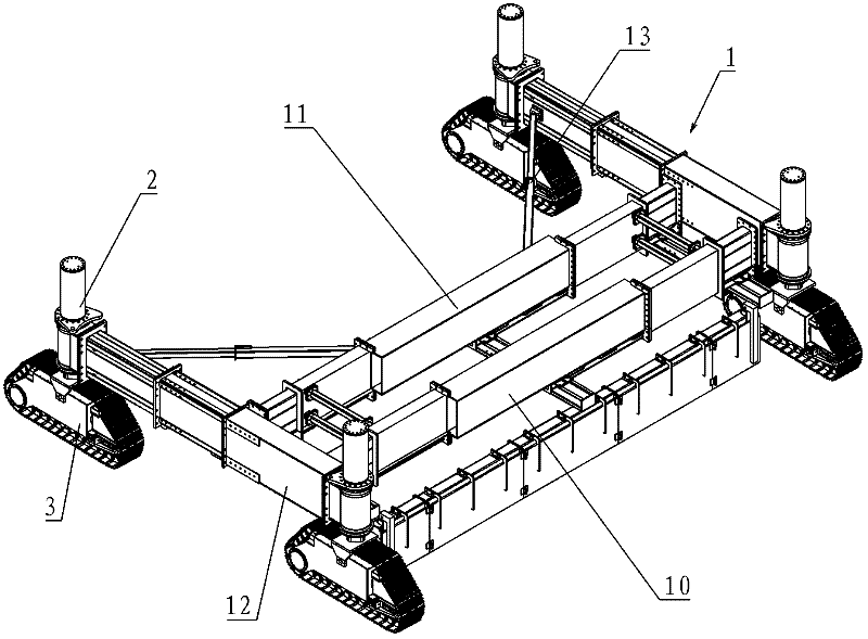
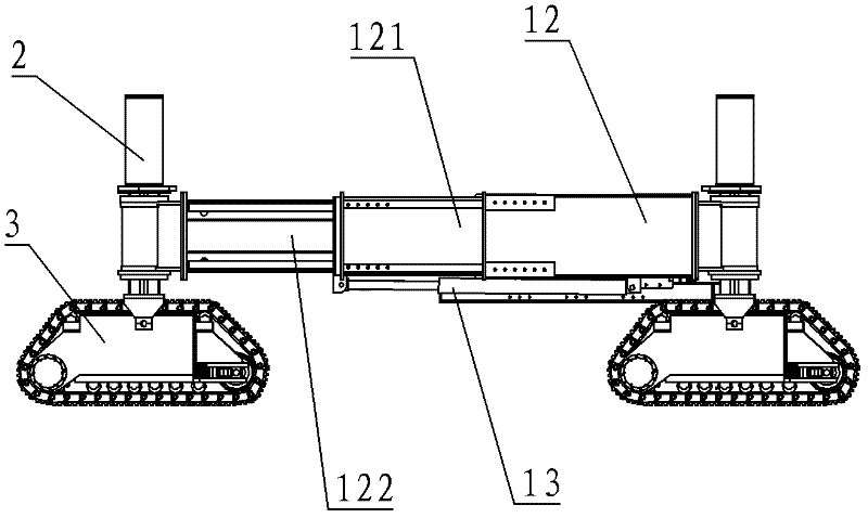
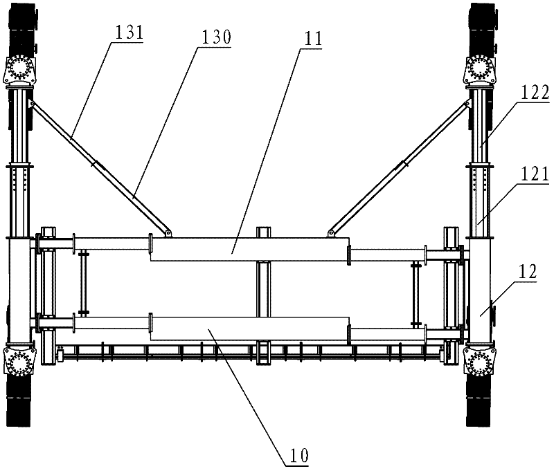
[0026] Such as figure 1 , figure 2 and image 3 As shown, the double telescopic frame 1 of the present embodiment includes a front beam 10, a rear beam 11, and side beams 12 installed on the left and right ends of the front beam 10 and the rear beam 11 to connect the front beam 10 and the rear beam 11. For ease of description, the direction parallel to the front beam 10 is defined as the transverse direction, and the direction parallel to the side beam 12 is defined as the longitudinal direction.
[0027] The front beam 10 in this embodiment is provided with a sliding sleeve type telescopic part (unlabeled) controlled by a hydraulic cylinder, and the rear beam 11 is also provided with a sliding sleeve type expansion part (unlabeled) controlled by a hydraulic cylinder. The sliding sleeve type telescopic part includes relatively movable inner and outer sliding sleeves and a hydraulic cylinder (not shown) that controls the lateral relative movement of the inner and outer slidi...
Embodiment 2
[0030] Such as Figure 4Shown is the double telescopic frame of Embodiment 2 of the present invention. The difference between Embodiment 2 and Embodiment 1 is that: an auxiliary side beam 12' is installed on the outside of the side beam 12, the structure of the auxiliary side beam 12' is the same as that of the side beam 12, and the first auxiliary side beam 12' is installed inside the auxiliary side beam 12'. The extension section 121' is installed on the free end of the first auxiliary extension section 121' through a flange connection with the installation column 2 of the crawler-type traveling device 3, and the first auxiliary extension section 121' can be mounted on the auxiliary side beam 12' The inner portion is extended or contracted longitudinally, and the expansion and contraction of the first auxiliary extension section 121' can also be controlled by a hydraulic cylinder or a screw rod. When the side beams 12 and the auxiliary side beams 12' are all extended, the d...
Embodiment 3
[0034] Such as Figure 8 As shown, the difference between embodiment 3 and embodiment 2 is that: the outer wall of the side beam 12 is equipped with a secondary side beam 12 ′ whose expansion and contraction direction is opposite to the expansion and contraction direction of the side beam 12 , and a first auxiliary extension The long section 121', the second auxiliary extension section 122' is installed in the first auxiliary extension section 121', and the installation column 2 on which the crawler-type traveling device 3 is installed is installed on the second auxiliary extension section 122' through flange connection The free end of the first sub-extension section 121' can be longitudinally elongated or contracted in the sub-side beam 12', and the second sub-extension section 122' can be longitudinally elongated in the first sub-extension section 121' or shrink. The structure and installation method of the auxiliary side beam 12', the first auxiliary extension section 121'...
PUM
 Abstract
Description
Claims
Application Information
 - R&D
- Intellectual Property
- Life Sciences
- Materials
- Tech Scout
- Unparalleled Data Quality
- Higher Quality Content
- 60% Fewer Hallucinations
Browse by: Latest US Patents, China's latest patents, Technical Efficacy Thesaurus, Application Domain, Technology Topic, Popular Technical Reports.
© 2025 PatSnap. All rights reserved.Legal|Privacy policy|Modern Slavery Act Transparency Statement|Sitemap|About US| Contact US: help@patsnap.com


