Electric rotary machine, armature, method of manufacturing electric rotary machine and machine for forming armature

a technology of electric rotary machines and armatures, which is applied in the direction of dynamo-electric components, windings, relays, etc., can solve the problems of increasing the number of man-hours, difficulty in ensuring a safety insulating distance, and increasing the number of insulation layers, so as to achieve high efficiency

Active Publication Date: 2010-08-31
DENSO CORP
View PDF6 Cites 3 Cited by
  • Summary
  • Abstract
  • Description
  • Claims
  • Application Information

AI Technical Summary

Benefits of technology

[0016]With such a structure mentioned above, since at least one of the lower and upper layer coil extensions includes the contour deformation part formed in the area at the intersecting region where the lower layer coil extension and the upper layer coil extension intersect with each other, the insulating distance can be provided between the lower layer coil extension and the upper layer coil extension at the intersecting region thereof. This makes it possible to adopt a thick flat type wire, that is, a flat type wire with an increased vertical length for a coil of an armature of an electric rotary machine, enabling a design of the electric rotary machine having a minimized structure with lightweight.
[0083]With such a structure stated above, the forming jig is inserted to between the upper and lower layer coil extensions, the lower layer coil extension can be prevented from bending radially inward. This results in reliable operation to form the contour deformation part of the upper layer coil extension in a highly efficient manner,

Problems solved by technology

However, it is well known that the flat type wire has a narrower creeping distance between upper and lower coils at an intersecting region where the upper and lower coils intersect with each other than that of a round wire with a difficulty encountered in ensuring a safety insulating distance.
Additionally, the flat type wire is hard to have a coil set (especially in the long side direction of the wire), causing an issue to arise in ensuring an insulating distance between the upper and lower coils at the intersecting region where the upper and lower coils intersect with each other.
These burrs are feared of causing damage to insulation layers of the coils with the resultant occurrence of short-circuiting.
When an attempt is made to deburr, the number of man-hour increases with the resultant increase in manufacturing cost.
This results in an increase of short-circuiting.
Thus, many number of press punching operations needs to be carried out with an increased load born by a press die, with a fear of shortening of die life.
Further, the burrs caused during press punching remain on the coils with adverse affects caused in subsequent steps.
Furthermore, the burrs, occurring during press punching, fly apart in equipment, resulting in an increase in labor hour for cleaning equipment.
This causes an increase in the number of component parts and production equipment becomes complicated in structure.

Method used


Image

  • Electric rotary machine, armature, method of manufacturing electric rotary machine and machine for forming armature
  • Electric rotary machine, armature, method of manufacturing electric rotary machine and machine for forming armature
  • Electric rotary machine, armature, method of manufacturing electric rotary machine and machine for forming armature

Examples


first embodiment

Modified Form of First Embodiment

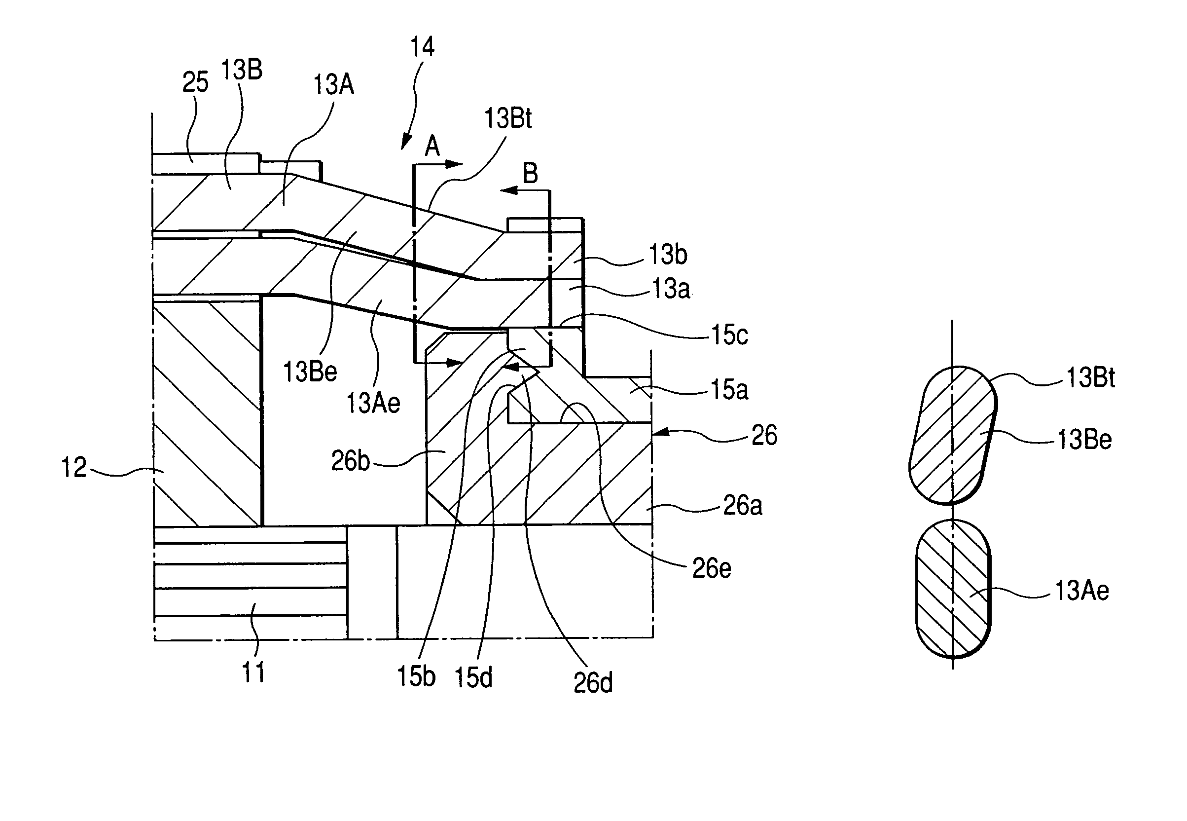
[0131]Now, a starter of a modified form of the first embodiment is described with reference to FIGS. 6A and 6B. FIG. 6A is an enlarged cross-sectional view partly showing an armature 14A forming part of the starter of the modified form of the first embodiment, wherein the slot 15c of the riser 15b of the conductor segment 15a accommodates therein the coil end portions 13a, 13b of the lower layer coil extension 13Ae and the upper layer coil extension 13Be, and FIG. 6B is a cross-sectional view showing coil end portions 13a, 13b.

[0132]The starter of the modified form of the first embodiment is described below with reference to an exemplary structure wherein the coil end portions 13a, 13b of the lower layer coil extension 13Ae and the upper layer coil extension 13Be inserted to the slot 15c of the riser 15b are bonded to each other by fusing.

[0133]Prior to fusing the coil end portions 13a, 13b of the lower layer coil extension 13Ae and the upper layer ...

second embodiment

Modified Form of Second Embodiment

[0170]While the present embodiment has been described above with reference to one example wherein the upper layer coil extension 13Be has the curvature portion 13Bc as the contour deformation part, an alternative may be possible to allow the lower layer coil extension 13Ae to have a curvature portion as a contour deformation part in shape similar to the curvature portion 13Bc of the upper layer coil extension 13Be. In another alternative, both the lower and upper layer coil extensions 13Ae, 13Be may have the curvature portions, respectively, like the curvature portion 13Bc.

[0171]While the forming machine 30 of the present embodiment has been set forth above with reference to a structure employing a single press punch 36, the forming machine 30 may be structured so as to have a plurality of press punch 36 in association with a whole of the coil insertion recesses 54 of the forming jig 34. With such an alternative, curvature portions 13Bc can be forme...


PUM


Abstract

An electric rotary machine, an armature for use in the electric machine, a method of forming an electric rotary machine and a forming machine for an armature of an electric rotary machine are disclosed wherein insulator-coated coils are wound in slots of an armature core from which lower and upper layer coil extensions extend and are connected to a commutator. The upper layer coil extension has a contour deformation part at an intersecting region where the lower and upper layer coil extensions intersect with each other to have an insulating distance between the lower and upper layer coil extensions. The forming machine includes a work holder holding the armature, and a forming jig forming a curvature portion on the upper layer coil extension.

Description

CROSS REFERENCE TO RELATED APPLICATIONS[0001]This application is based on Japanese Patent Application Nos. 2005-348687, filed on Dec. 2, 2005, and 2005-378775, filed on Dec. 28, 2005, the contents of which are hereby incorporated by reference.BACKGROUND OF THE INVENTION[0002]1. Technical Field of the Invention[0003]The present invention relates to electric rotary machines having armature coils made of flat type wires and, more particularly to an electric rotary machine, an armature for the electric rotary machine, a method of manufacturing the electric rotary machine and a forming machine for the armature of the electric rotary machine.[0004]2. Description of the Related Art[0005]In recent years, an electric rotary machine (especially a starter) for installation on a vehicle requires an effort to minimize a structure with lightweight aimed at decreasing an installation space and improving fuel consumption. To achieve such an aim, an attempt is made to provide a model an armature coi...

Claims


Application Information

Patent Timeline
Patent Type & Authority Patents(United States)
IPC IPC(8): H02K23/26H02K3/46
CPCH02K3/12H02K13/04H02K15/0037
Inventor KITOU, KAZUYUKIITOH, AKIYASUINOUE, KATSUNOBUSAKAI, EIJIFUKUI, MINORU
Owner DENSO CORP
Why Eureka
Try Eureka