
Windproof construction device with high bridge piers

A technology for construction devices and high bridge piers, applied in bridges, bridge parts, bridge construction, etc., can solve the problems of prolonging the construction period, increasing the pump power, generating grooves and seams on the surface of the pier body, and staggering the platform, so as to ensure the strength and quality. The effect of increasing bending stiffness and wind resistance is obvious

Inactive Publication Date: 2013-05-22
SOUTHWEST JIAOTONG UNIV
View PDF5 Cites 0 Cited by
  • Summary
  • Abstract
  • Description
  • Claims
  • Application Information

AI Technical Summary

Problems solved by technology

Both of these two windproof methods have the following disadvantages: 1. The setting of the windshield requires pre-embedded connectors on the pier body. If the treatment is not in place after completion, it is easy to have a certain impact on the shape of the pier
3. Adding a maintenance structure outside the outer support formwork of the pier increases the amount of construction work and prolongs the construction period; and if the ring-shaped windshield is set to surround the entire construction site of the pier, the construction operations are all carried out within the windproof maintenance structure. There are also shortcomings such as inconvenient transportation of construction materials, increasing the difficulty of construction, increasing the conveying height and distance of the concrete pump, increasing the power of the pump, and increasing the cost of construction.
However, due to the limited rigidity and number of elongated bolts, in the case of high piers, the side pressure of the pier wall due to the self-weight and expansion of the concrete may still occur when pouring concrete, which will lead to the instability of the formwork and the occurrence of mold expansion and grout leakage Etc., affect the quality of poured concrete; cause the pier to shift and twist, the surface of the pier body will produce grooves, staggered platforms, and the pier body will change slopes, reducing the strength of the pier and affecting the quality of the pier
And after pouring in this way, the PPC holes reserved on the pier will affect the appearance, and the holes need to be refilled, which prolongs the construction period

Method used


Image

  • Windproof construction device with high bridge piers
  • Windproof construction device with high bridge piers

Examples


Embodiment

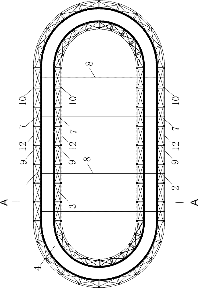
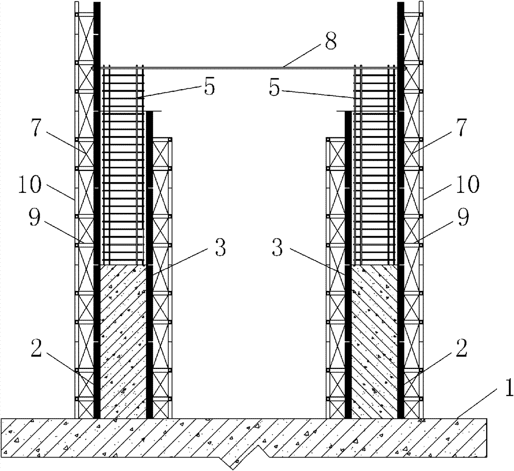
[0022] figure 1 , 2 It is shown that a specific embodiment of the present invention is: a high bridge pier windproof construction device, comprising an inner formwork 3 and an outer formwork 2 arranged at the inner and outer positions of the reinforcement cage 5 on the pier cap 1, which is characterized in : The outer formwork 2 is 31.3-1.8m higher than the inner formwork; the inside of the inner formwork 3 and the outside of the outer formwork 2 are fixedly connected.

[0023] figure 2 As shown, the outer formwork 2 is composed of a lower part equal to the inner formwork 3 and an upper part higher than the inner formwork 3, and the upper and lower parts are fixed by bolts.

[0024] figure 1 , 2 As shown, the top of the reinforcing steel cage 5 is connected with a detachable pair of tie rods 8 transversely, that is, a direction perpendicular to the long side of the pier, and the ends of the pair of tie rods 8 are fixed on the outer formwork 2.

[0025] The specific composition of t...


PUM


Abstract

The invention discloses a windproof construction device with high bridge piers. The device comprises an inner mould board (3) and an outer mould board (2), wherein the inner mould board (3) and the outer mould board (2) are arranged on the inner side and the outer side of a steel reinforcement cage (5) on a pier stud carrying table (1), and the windproof construction device with the high bridge piers is characterized in that the outer mould board (2) is 1.3-1.8m higher than the inner mould board (3); and the inner side of the inner mould board (3) and the outer side of the outer mould board (2) are fixedly connected with windproof trusses. When in construction of the bridge piers under severe weather at high wind velocity, the device can enable the pouring quality of concrete and the strength of the bridge piers is high; and furthermore, the structure is simple, the construction is easy and the cost is low.

Description

Technical field [0001] The invention relates to a bridge construction device, in particular to a high bridge pier windproof construction device under high wind speed. Background technique [0002] Most high bridge piers are in the form of elliptical (ring) hollow piers. The usual construction method is as follows: Place a cylindrical double-layer steel cage on the pier cap. Inside and outside the cylindrical steel cage, there are internal and external support templates of equal height to facilitate the construction in the lining. Concrete pouring. Due to the poor integrity of the assembled formwork, it may deform or even collapse under the action of strong wind. In addition, due to height restrictions, the pouring construction of the high bridge piers cannot generally be completed at one time, so it must be poured in sections. In this way of construction in stages, in case of severe weather conditions with high wind speeds, after a section of construction is completed, because...

Claims


Application Information

Patent Timeline
Patent Type & Authority Patents(China)
IPC IPC(8): E01D21/00E01D19/02
Inventor 李永乐任红全廖海黎
Owner SOUTHWEST JIAOTONG UNIV
Learn More