A crane hydraulic system and its hydraulic balance valve

A technology of hydraulic balance and main valve body, which is applied in the field of crane hydraulic system and hydraulic balance valve, can solve the problems of unstable operation of the operator, left and right vibration of the main valve core, sudden acceleration, etc., and achieve high operating comfort, safety and reliability. performance, avoid hydraulic shocks, small pressure fluctuations

Inactive Publication Date: 2011-11-30
XUZHOU HEAVY MASCH CO LTD
View PDF3 Cites 10 Cited by
  • Summary
  • Abstract
  • Description
  • Claims
  • Application Information

AI Technical Summary

Problems solved by technology

[0006] However, when the steel ball 132 in the control end cover 11 is closed, the control oil is suddenly blocked, resulting in a short-term hydraulic shock, which cannot smoothly control the reversing of the spool 121 during the opening process. At this time, It will cause the control pressure of the control spool 121 to fluctuate violently. Since the control spool 121 is reset by the spring force, the pressure fluctuation will cause the spring 131 to vibrate, and finally cause the main spool to vibrate from side to side, making the opening of the valve port fluctuate. , that is, the moving speed of the main spool will change suddenly during the reversing or moving process, which may cause hydraulic shock, cause crawling and sudden acceleration of the hydraulic actuator, and cause the structural parts to vibrate, thus causing serious damage to the operator. Operational instability and discomfort can easily lead to operational errors and safety accidents
When the balance valve is applied to the lifting system of a mobile crane, this failure will appear as a sudden stop or a sudden increase in the speed of the hydraulic motor during the rotation process, which will cause a sudden stop or sudden lifting of the heavy object, and the related structural components will also be damaged. produce trembling

Method used


Image

  • A crane hydraulic system and its hydraulic balance valve
  • A crane hydraulic system and its hydraulic balance valve
  • A crane hydraulic system and its hydraulic balance valve

Examples


Embodiment Construction

[0028] The core of the present invention is to provide a hydraulic balance valve. When the hydraulic balance valve closes the control oil, there is a buffering process, which avoids the generation of pressure shock and makes the control pressure relatively stable, so that the valve core can be smoothly controlled to change direction. Another core of the present invention is to provide a crane hydraulic system including the above-mentioned hydraulic balance valve.

[0029] In order to enable those skilled in the art to better understand the technical solutions of the present invention, the present invention will be further described in detail below in conjunction with the accompanying drawings and specific embodiments.

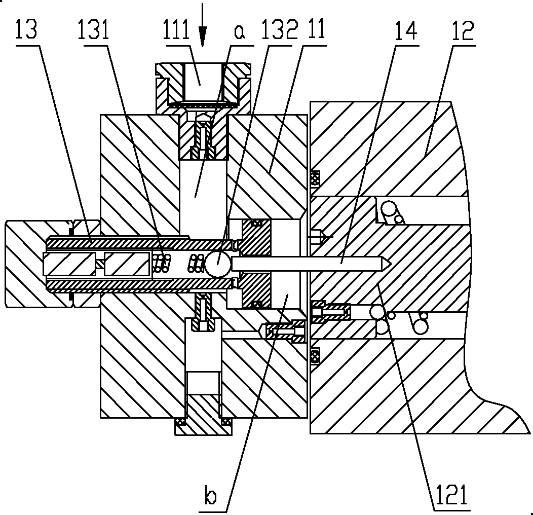
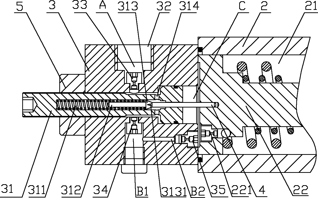
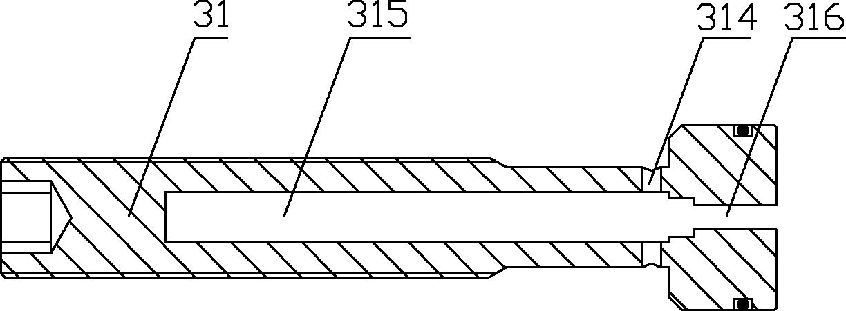
[0030] Please refer to Figure 2 to Figure 6 , figure 2 It is a structural schematic diagram of a specific embodiment of the hydraulic balance valve provided by the present invention. This figure only shows the control valve cover and the control valve core, ...


PUM


Abstract

The invention discloses a hydraulic balance valve, which comprises a control valve cover and a main valve body. The control valve cover has a stepped blind hole opposite to and coaxial with the control valve core, and the control valve cover is provided with a large-diameter section communicating with the blind hole. The small-diameter section of the blind hole is connected to the cavity, and the large-diameter section is equipped with a plugging part for blocking the small-diameter section. A throttling groove is arranged on the plugging matching surface of the small diameter section, and the cross-sectional area of ​​the throttling groove increases along the axial direction. In the process of closing the oil channel where the control oil enters, the flow rate through the throttling groove will gradually decrease, which can effectively avoid the generation of hydraulic shock. Therefore, the pressure fluctuation of the control oil acting on the control valve core is relatively small. Small, the opening of the main spool will not fluctuate, which can eliminate jitter, and has high operating comfort, safety and reliability. The invention also discloses a crane hydraulic system comprising the hydraulic balance valve.

Description

technical field [0001] The invention relates to the technical field of engineering machinery, in particular to a hydraulic balance valve. The present invention also relates to a crane hydraulic system comprising the above-mentioned hydraulic balance valve. Background technique [0002] Improving the safe operating performance of cranes has always been a technical issue that technicians in this field have devoted themselves to studying. At present, in the hoisting, luffing and telescopic systems of cranes, balance valves are used for hydraulic locking to ensure that the load can reliably stay at any position and avoid the movement of the load due to internal leakage of hydraulic components. Therefore, the balance valve is usually used as a balance and safety device to control the load-bearing lowering speed of the crane. [0003] The safe working principle of the balance valve is as follows: when the balance valve is opened in the forward direction, the hydraulic oil direct...

Claims


Application Information

Patent Timeline
Patent Type & Authority Applications(China)
IPC IPC(8): F15B13/02B66C13/20
Inventor 史先信刘邦才张党辉王清送
Owner XUZHOU HEAVY MASCH CO LTD
Why Eureka
Try Eureka