Automatic Balance Valve Control

a technology of automatic balance valve and balance valve, which is applied in the direction of space heating and ventilation, lighting and heating apparatus, heating types, etc., can solve the problems of difficult to achieve the effect of stable temperature difference, many iterations, and difficult to achieve the effect of balancing the system

Active Publication Date: 2018-02-01
COMPUTIME LTD
View PDF23 Cites 7 Cited by
  • Summary
  • Abstract
  • Description
  • Claims
  • Application Information

AI Technical Summary

Problems solved by technology

This process of balancing an environmental temperature control system is often quite tedious and may require numerous iterations in order to fine tune a balanced system.
The time required to balance a system may be extremely long with a more complicated configuration.

Method used


Image

  • Automatic Balance Valve Control
  • Automatic Balance Valve Control
  • Automatic Balance Valve Control

Examples


Embodiment Construction

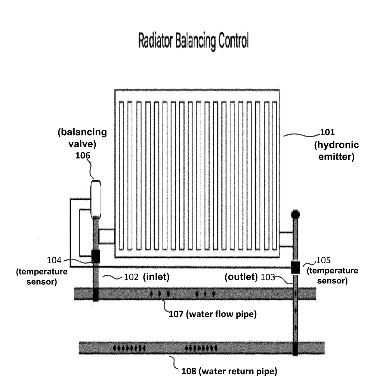
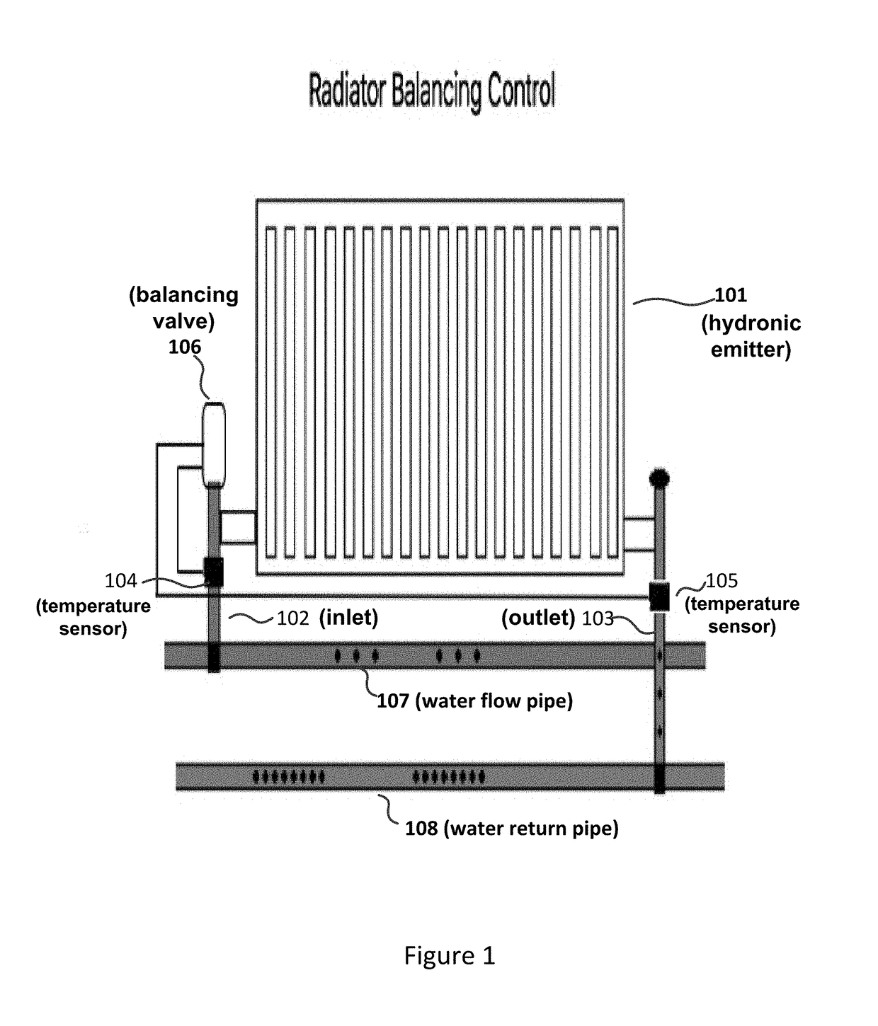
[0018]FIG. 1 shows balance valve 106 that controls heated / cooled water flow for radiator (hydronic emitter) 101 in accordance with an embodiment. As will be discussed, balance valve 106 self-adjusts the water flow through radiator 101 to achieve a desired temperature differential between inlet 102 and outlet 103.

[0019]Balance valve 106 may support heating and / or cooling environmental systems. When supporting a heating mode, water flow pipe 107 transports heated water to radiator 101 through inlet 102. When supporting a cooling mode, water flow 107 transports cooled water. Water return pipe 108 returns the expended water from radiator 101 through outlet 103.

[0020]Balance valve 106 measures the inlet and outlet temperatures through temperature sensors 104 and 105, respectively, and adjusts the water flow through radiator 101 so that the measured temperature differential stabilizes to the desired temperature differential. For example, when balance valve 106 is operating in the heating ...


PUM


Abstract

A self-adjusting balance valve controller controls water flow through a hydronic emitter in a heating and / or cooling temperature control system. The valve controller obtains a measured temperature differential between an inlet and an outlet of the hydronic emitter and determines a displacement of a coupling pin from the measured temperature differential. The valve controller then instructs a driving mechanism to move, through a coupling mechanism, the coupling pin to adjust a valve that results in a desired water flow through the hydronic emitter. The valve controller may maintain a stable temperature differential at a desired differential value, which may be obtained through a user interface or from a memory device. Moreover, the desired differential value may vary with different times of operation or temperature control situations.

Description

[0001]This patent application claims priority to U.S. provisional patent application Ser. No. 62 / 367,268 entitled “Automatic Balance Valve Control” filed on Jul. 27, 2016, which is hereby incorporated by reference in its entirety.TECHNICAL FIELD[0002]Aspects of the disclosure relate to a self-adjusting balance valve controller for controlling water flow through a hydronic emitter (e.g., radiator) in an environmental temperature control system.BACKGROUND OF THE INVENTION[0003]For hydronic emitters (including radiators, underfloor heating / cooling circuits, fan coils, chilled beams) the rate at which the water flows through the emitters need to be regulated to ensure all circuits / emitters in an environmentally temperature controlled system are balanced. The water flow varies due to different distances, connection circuitry and size of the pipes from the water pressure source or water pump. In order to make the system work in balance, a mechanical or fixed flow restricting valve may be ...

Claims


Application Information

Patent Timeline
Patent Type & Authority Applications(United States)
IPC IPC(8): F24D19/10F24D3/02
CPCF24D3/02F24D19/1018F24D2220/0257F24D2220/0264F24F11/70
Inventor SMITH, PHILIP JOHNHA, WAI-LEUNGJEPSON, DEAN RICHARDCHENG, CHUNG-MINGKAM, KWOK WA KENNYHUANG, HAO-HUICHAN, DICK KWAILIAO, HONG BIN
Owner COMPUTIME LTD
Why Eureka
Try Eureka