A high-pressure cut-off/drainage spherical core valve

A ball core, high-pressure technology, applied in the direction of valve details, valve device, valve housing structure, etc., can solve the problems of excessive torque, etc., to achieve the effect of prolonging service life, high reliability, and avoiding leakage

Active Publication Date: 2011-11-30
SHANDONG MINGDUN EXPLOSION PROOF EQUIP TECH CO LTD
View PDF5 Cites 0 Cited by
  • Summary
  • Abstract
  • Description
  • Claims
  • Application Information

AI Technical Summary

Problems solved by technology

The principle of pressure balance is adopted, and channels of the same aperture are cleverly opened on both sides of the valve core in the valve body, which effectively solves the problem of excessive torque. The pressure is applied to the opposite side of the force-bearing surface, so that the pressure on the valve core is balanced. , so that the rotation of the spool is flexible and not easy to wear

Method used


Image

  • A high-pressure cut-off/drainage spherical core valve
  • A high-pressure cut-off/drainage spherical core valve
  • A high-pressure cut-off/drainage spherical core valve

Examples


Embodiment 1

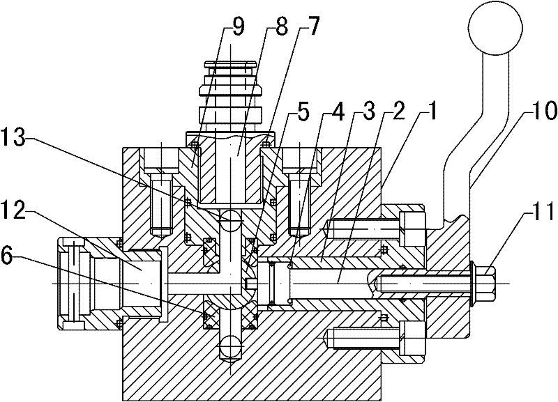
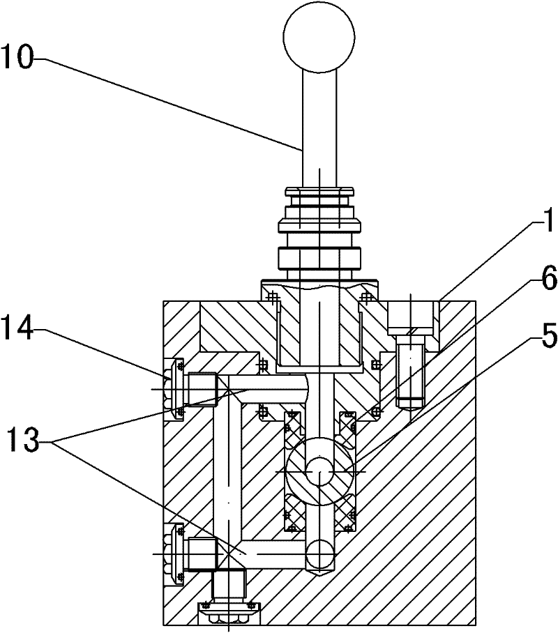
[0020] Refer to attached Figure 1~2 : Used as blowdown valve

[0021] The high-pressure cut-off / drainage spherical core valve includes a valve body 1, a valve core 5 and a valve seat 6. The valve core 5 is installed in the valve body 1 through the valve seat 6. The valve core 5 is spherical and has a keyway. The valve body 1 has two The side is provided with a liquid inlet 8 and a liquid outlet 12, the liquid inlet 8 is set on the upper surface of the valve body 1 and is threaded to connect the quick plug, the liquid outlet 12 is set on one side of the valve body 1 and is threaded to the quick socket, the liquid inlet 8 and the liquid outlet 12 communicate with the through hole in the spool 5, and two pressure balance passages 13 of equal aperture are added symmetrically on the upper and lower sides of the center of the spool 5 in the valve body 1, and the two pressures are balanced. One end of the channel 13 communicates with the main channel in the valve body 1 respectivel...

Embodiment 2

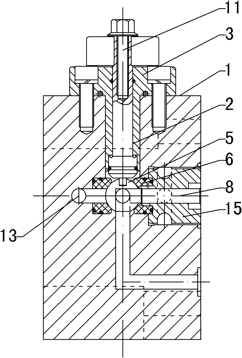
[0026] Refer to attached Figure 3-5 : Used as a stop valve

[0027] The utility model can also be used in the automatic backwashing system of the filter, and can be used as a cut-off valve, that is, the backwashing valve in the backwashing system; the liquid inlet 8 is arranged on the front surface of the valve body 1, and the liquid outlet 12 is arranged on the liquid inlet 8, on the same plane as the liquid inlet 8, the liquid inlet 8 is connected to the integrated valve seat system of the filter, the liquid outlet 12 is connected to the recoil pipe of the filter, and the valve body 1 at the liquid inlet 8 is equipped with a threaded sleeve 15 , Two pressure balance passages 13 are set in the valve body 1, on the left and right sides of the center of the valve core 5.

[0028] The working principle and working process are the same as those in Embodiment 1.


PUM


Abstract

The invention discloses a high-pressure stop/ pollution discharge ball core valve, belonging to the field of high-pressure valve devices. The valve comprises a valve body (1) and a valve core (5); the valve core (5) is of a ball shape, and is provided with a key slot; and a liquid inlet (8) and a liquid outlet (12) are arranged outside the valve body (1). The valve is characterized in that the valve core (5) is installed in the valve body (1) through a valve seat (6); the valve core is connected with a handle (5) or a speed reduction motor through a rotary shaft (2); two pressure balance channels (13) which are communicated with each other and have equal apertures are arranged at two sides of the valve core (5) in the valve body (1); one end of each pressure balance channel (13) is communicated with a main channel in the valve body (1), and the other end of each pressure balance channel (13) is sealed with a seal screw (14) and a seal ring (7), and thus a closed water groove is formed. The valve has the advantages of flexible opening, reliable sealing and small rotation torque, and can be used in fluid with high pressure and serious pollution, and the valve can be used alternatively under program automatic control and manual control.

Description

technical field [0001] A high-pressure cut-off / drainage spherical core valve belongs to the field of high-pressure valve devices. Background technique [0002] At present, ball core valves are widely used in water pipes and related switches and flow control. There are two structures of existing ball core valves. One is that the ball core is separated from the shaft, that is, a spherical valve core is installed in the middle of the valve body. There is a groove on the top of the spool, and the shaft plugged into the groove is sealed by a sealing ring, and the shaft extends to the outside of the valve body. The inlet and outlet of the valve correspond to the channels in the spool. The shaft is integrated; there is a problem in these two types of valves, that is: the friction between the valve core and the parts in the valve body is relatively large, and the valve core is under a certain pressure, and there is a problem of excessive rotational torque. The inside of the body is...

Claims


Application Information

Patent Timeline
Patent Type & Authority Applications(China)
IPC IPC(8): F16K5/06F16K27/06
Inventor 冯宝令盛宝祥王志涛
Owner SHANDONG MINGDUN EXPLOSION PROOF EQUIP TECH CO LTD
Why Eureka
Try Eureka