Fault Identification and Orientation Detection in Three-Phase Power Systems

A three-phase power and power system technology, applied in the fault location, detecting faults according to conductor types, measuring electricity and other directions, can solve the problem of not guaranteeing the distinction between two-phase grounding faults and single-phase grounding faults, and fault detection equipment is not suitable for widespread implementation. And other issues

Active Publication Date: 2011-11-30
SCHNEIDER ELECTRIC IND SAS
View PDF8 Cites 7 Cited by
  • Summary
  • Abstract
  • Description
  • Claims
  • Application Information

AI Technical Summary

Problems solved by technology

[0007] Therefore, it is evident that existing fault detection devices are not suitable for widespread implementation, given their complexity, especially the number of sensors required when two-phase sites are assembled
Moreover, for less complex detection equipment comprising only the current sensor 12, in some applications, especially depending on the neutral system, the distinction between two-phase-to-earth faults and single-phase-to-earth faults cannot be guaranteed

Method used


Image

  • Fault Identification and Orientation Detection in Three-Phase Power Systems
  • Fault Identification and Orientation Detection in Three-Phase Power Systems
  • Fault Identification and Orientation Detection in Three-Phase Power Systems

Examples


Embodiment Construction

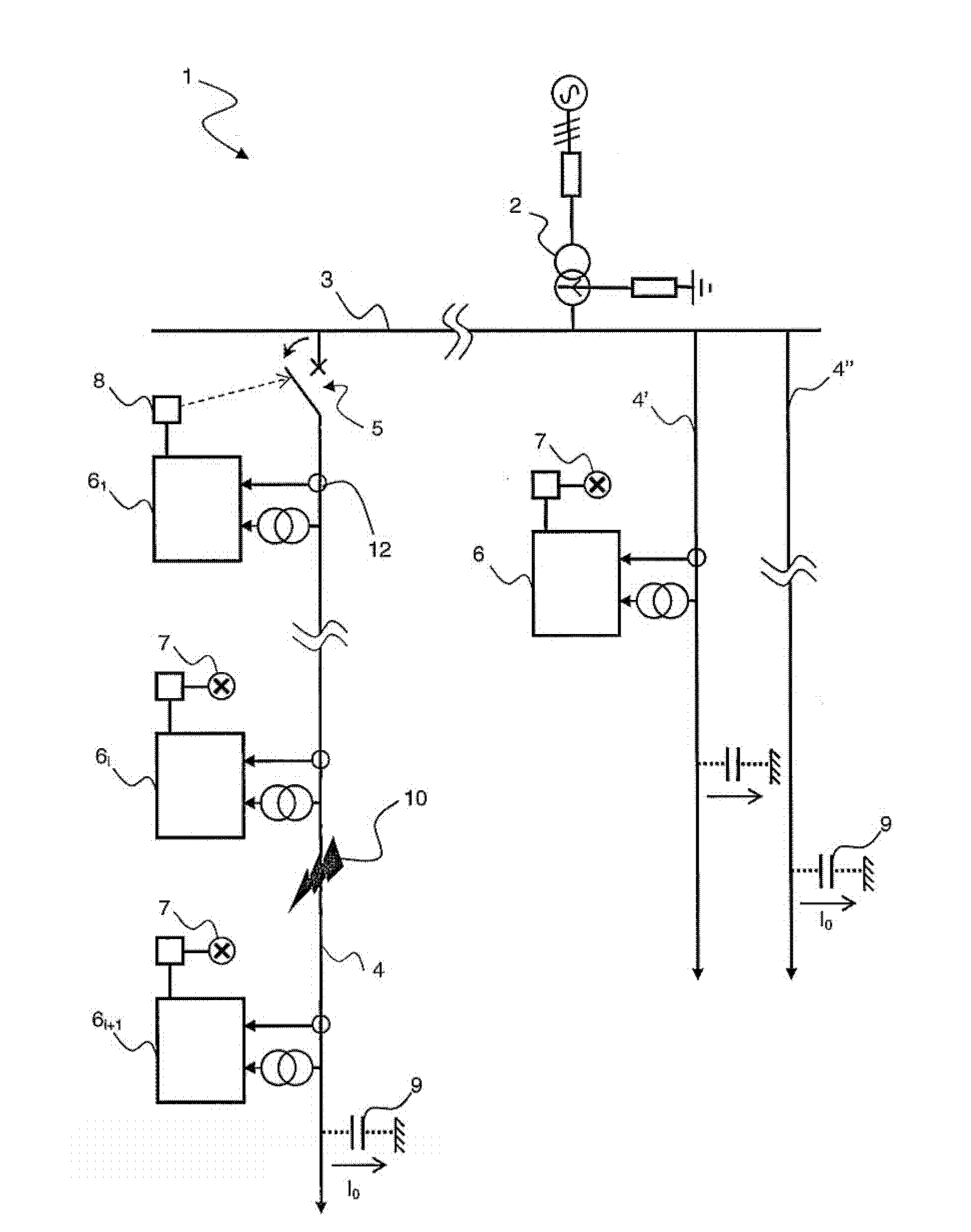
[0031] The directional detection device 15 for a fault 10 according to the invention can replace the existing device 6 and be used in applications such as those described in figure 1 Any three-phase power system 1 of that kind. In particular, although the description refers to a power system 1 with a natural frequency F=50 Hz, the arrangement and method according to the invention are directly adaptable to other frequencies. The description hereinafter will be directed to a balanced power system 1, that is, in the absence of faults, the zero-sequence current I 0 is made in zero cases, but this is by no means restrictive.

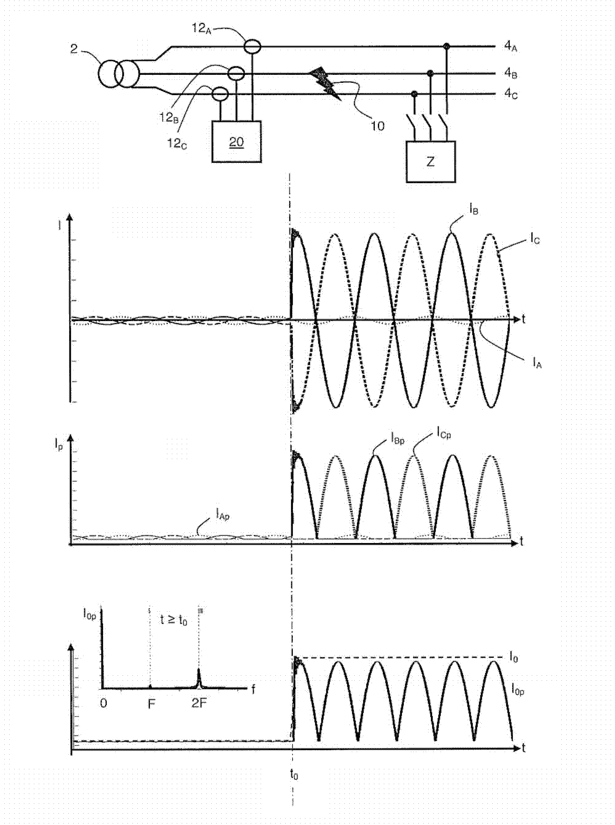
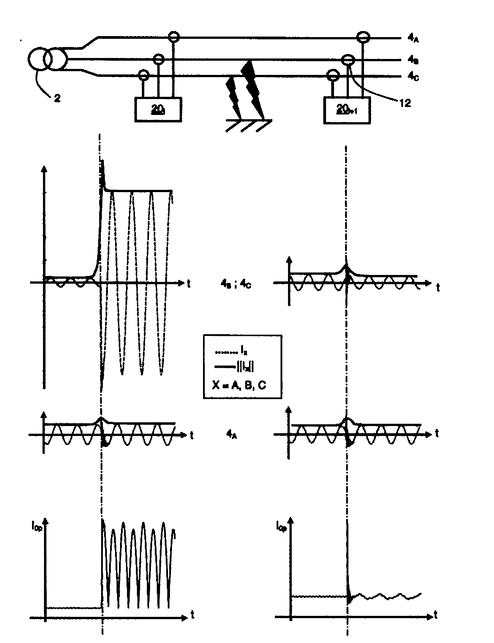
[0032] Such as figure 2 As shown, the device 20 provides a three-phase conductor 4 representing the incoming line 4 A 、4 B 、4 C One or more signals of the current in each root. The current measuring device 20 advantageously forms part of the device 15 fitted on said line 4 according to the invention and is connected to the measuring device directly on ...


PUM


Abstract

The device (15) has a current representative parameter processing unit (30) with a computing unit (44) to compute current resulting from sum of parameter and resultant frequency analysis units (46, 48) with comparison of zero harmonic components (I0pDC) and two harmonic components (I0p 2F) with respect to proper frequency of a three-phase network. Activation units (32) activate the processing units based on a defect occurrence detection signal (D) in the network, and interpretation units (40) interpret processing results with the processing unit to determine if defect is biphasic. Independent claims are also included for the following: (1) a short circuit default indicator comprising current sensors arranged on each phase conductor (2) a method for identifying defect in a three-phase network (3) a method for identifying and relative localization of defect in a three-phase network (4) a method for protecting a current line.

Description

technical field [0001] The present invention relates to the identification and directed detection of faults between two phases of a three-phase power system without measuring line voltage. In particular, the present invention relates to a method of detecting a two-phase fault in a power system and further being able to determine whether the fault is on the line side or the load side of the detection point. The method according to the invention is based on a unique signal representing the current of each phase of the power system, the processing of which leads to parameters enabling orientation. The two-phase detection method for two-phase faults can be coupled with other steps to identify and locate single-phase or three-phase faults. [0002] According to another feature, the invention concerns a detection device designed to carry out the method described above. In particular, the directional fault detection device comprises means for calculating parameters from the current...

Claims


Application Information

Patent Timeline
Patent Type & Authority Applications(China)
IPC IPC(8): G01R31/02G01R31/08
CPCG01R31/085G01R31/088H02H3/347
Inventor 帕斯卡尔.库姆内尔纪尧姆.沃尼奥
Owner SCHNEIDER ELECTRIC IND SAS
Why Eureka
Try Eureka