A signal transmission system and method for realizing automatic error correction for code errors

An automatic error correction and signal technology, applied in the field of communication signal transmission, can solve the problems of low signal transmission efficiency and high bit error rate of signal transmission, and achieve the effect of improving signal transmission efficiency and reducing bit error rate.

Inactive Publication Date: 2011-11-30
SUZHOU DEMAC ELECTRIC
View PDF4 Cites 2 Cited by
  • Summary
  • Abstract
  • Description
  • Claims
  • Application Information

AI Technical Summary

Problems solved by technology

[0006] The technical problem to be solved by the present invention is: the existing signal transmission bit error rate is relatively high, resulting in low signal transmission efficiency

Method used


Image

  • A signal transmission system and method for realizing automatic error correction for code errors
  • A signal transmission system and method for realizing automatic error correction for code errors
  • A signal transmission system and method for realizing automatic error correction for code errors

Examples


Embodiment Construction

[0032] Preferred embodiments of the present invention will be described in detail below in conjunction with the accompanying drawings.

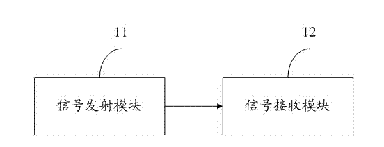
[0033] see figure 1 , which is a schematic diagram of an embodiment of a signal transmission system for automatic error correction for code errors in the present invention.

[0034] The present invention provides a signal transmission system for realizing automatic error correction for code errors, which includes: a signal transmitting module 11 and a signal receiving module 12 . The signal transmitting module 11 and the signal receiving module 12 may be connected by wire or wirelessly. The signal transmitting module 11 is used for encoding the signal to be transmitted and then transmitting it. The signal receiving module 12 is used for correspondingly decoding the received signal.

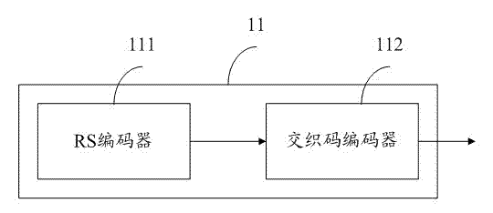
[0035] see figure 2 , which is the invention figure 1 The schematic diagram of the signal transmitting module 11 is shown.

[0036] The signal transmittin...


PUM


Abstract

The invention discloses a signal transmission system for realizing automatic error correction for code errors. The signal transmission system for implementing automatic error correction for code errors includes a signal transmitting module and a signal receiving module, and the signal transmitting module includes an RS encoder for performing RS encoding on a signal and an RS encoder for performing RS encoding on a signal. An interleaving code encoder for performing interleaving encoding on signals; the signal receiving module includes an interleaving code decoder for interleaving code decoding of signals transmitted by the interleaving code encoder and RS for signals transmitted by the interleaving code decoder decoded RS decoder. The invention has the beneficial effects of reducing the error rate of signal transmission and improving the efficiency of signal transmission.

Description

technical field [0001] The invention relates to the technical field of communication signal transmission, in particular to a signal transmission system and method for realizing automatic error correction for code errors. Background technique [0002] With the maturity of wireless communication technology and the requirements of large-scale, decentralized and complex industrial control, wireless communication, as a supplement to traditional fieldbus, has begun to be used more and more in the field of industrial control. Especially for the industrial sites where the control nodes are widely distributed, it is difficult to lay communication lines, or there are moving objects, such as mobile machinery equipment, open-pit coal mine production scheduling system and metropolitan rail transit management system, etc., the communication connection must be established in a wireless way. [0003] Compared with wired network, the anti-interference ability of wireless communication networ...

Claims


Application Information

Patent Timeline
IPC IPC(8): H04L1/00H04W28/04
Inventor 王棱馨
Owner SUZHOU DEMAC ELECTRIC
Why Eureka
Try Eureka