Internal broaching tools

A tool, rough drawing technology, applied in the direction of manufacturing tools, gear teeth manufacturing tools, broaches, etc., can solve the problem that the side shape can no longer be corrected.

Inactive Publication Date: 2011-11-30
德国采拉梅里斯特殊刀具有限公司
View PDF6 Cites 2 Cited by
  • Summary
  • Abstract
  • Description
  • Claims
  • Application Information

AI Technical Summary

Problems solved by technology

[0038] However, in addition to the disadvantages that occur similarly to the solution according to document EP 0739674 A1, another disadvantage results, which is that, with the solution proposed in document EP 1 317 982 B1, due to the one-sided Finishing (Schlichtbearbeitung), side shape corrections are no longer possible during the broaching process (e.g. tooth profile with high sphericity correction for improving the running behavior of the toothing), since lateral form corrections always have to be carried out on both sides

Method used


Image

  • Internal broaching tools
  • Internal broaching tools
  • Internal broaching tools

Examples


Embodiment Construction

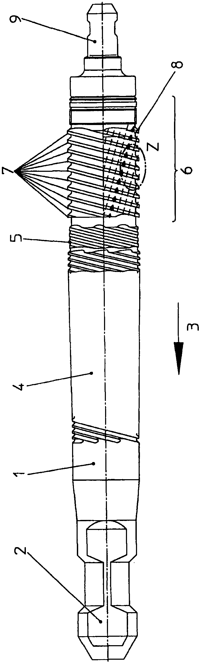
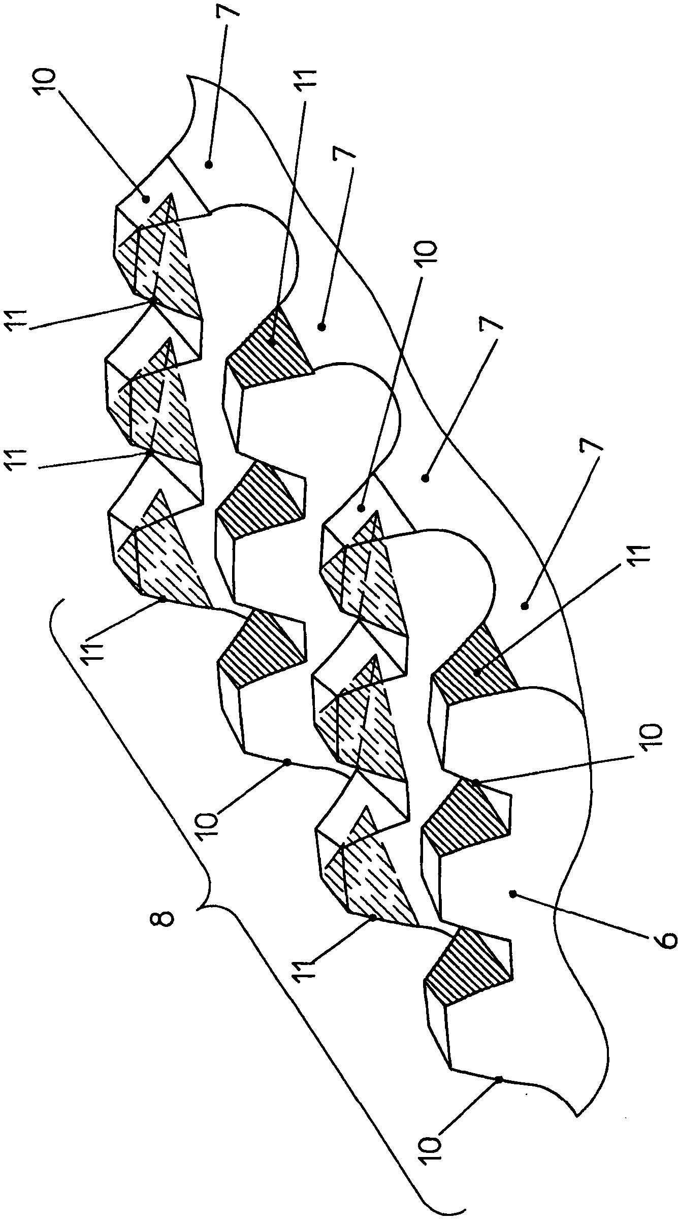
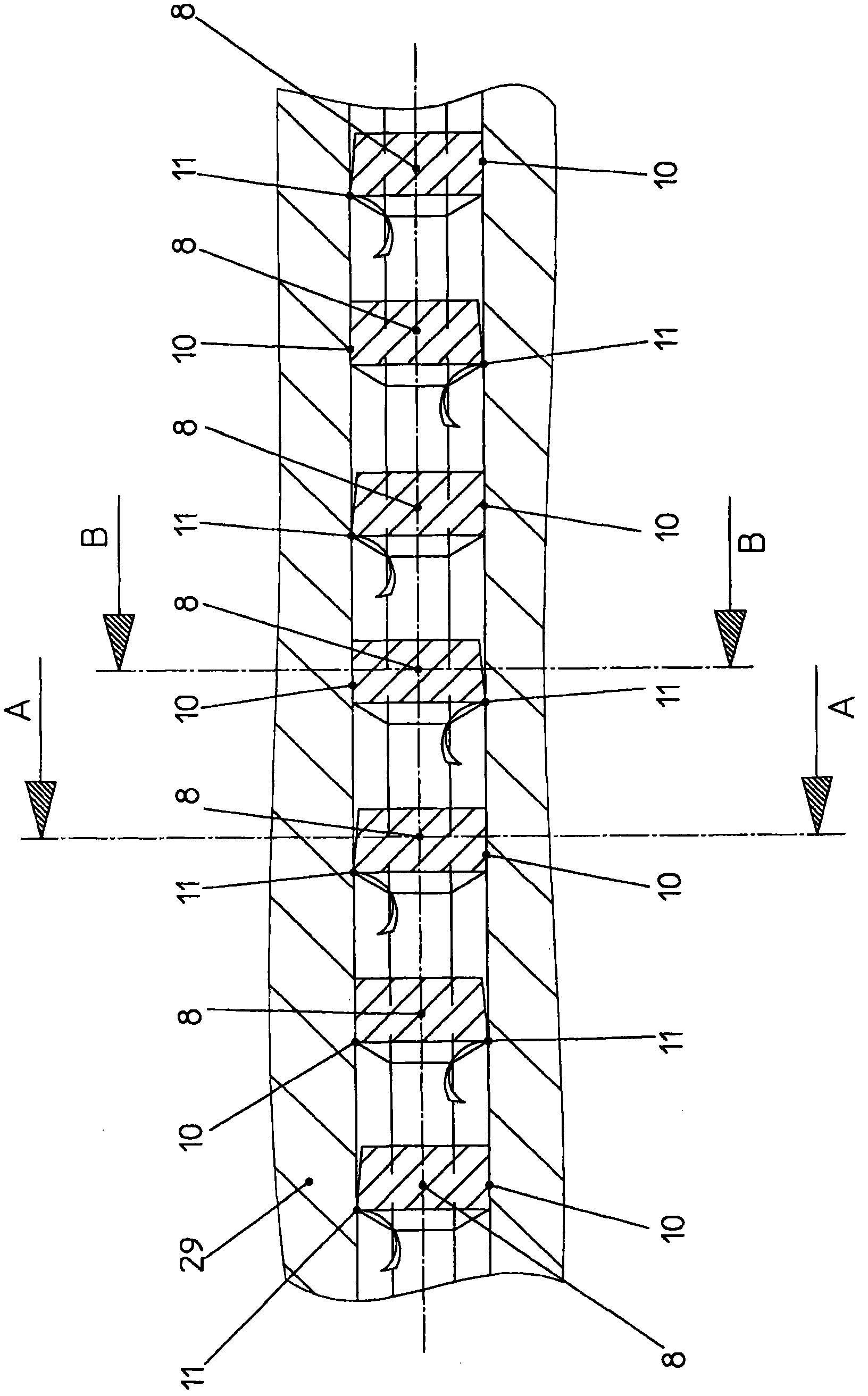
[0057] exist figure 1 shows an internal broaching tool 1 according to the invention for internal broaching of an internal toothing with a profile base and a profile side, the internal broaching tool 1 comprising: a shank 2; opposite to the broaching direction 3 A toothed part 4 arranged adjacent to the shank 2 with a plurality of broaching teeth arranged in succession in a row (Reihen) with contour base edges associated with one another for pre-broaching (rough broaching) profile; opposite to the broaching direction 3 there follows a correcting part 6 with a plurality of correcting broaching teeth 8 arranged successively in a row 7; An unloading section 5 is arranged between the correction section 6 and the correction section 6 .

[0058] This arrangement according to the invention of the unloading part 5 unloads the workpiece before corrective machining, so that the deformation of the workpiece caused by the cutting forces occurring during broaching is not eliminated after t...


PUM


Abstract

The invention relates to an internal broaching tool for broaching profiles delimited by a root and flanks. The aim of the invention is to design an internal broaching tool for broaching profiles that allows a workpiece to be broached in an inexpensive, robust, simple, functionally safe, and reliable manner without requiring a machining allowance while ensuring great accuracy of the shape and flanks of the profile on the broached workpiece even when the material strength of the workpiece changes, such that the actually broached profile exactly matches the desired profile. The internal broaching tool as per the invention is characterized in that a relief part (5) is arranged between the toothed part (4) and the calibration part (6), and the calibrating broaching teeth (8) in adjacent rows (7) on the calibration part (6) are designed such that said teeth (8) have a guiding flank (10) (without a clearance angle or with a maximum negative clearance angle of 0.1 DEG ) and a cutting flank (11) (with a positive clearance angle), and the guiding flanks (10) and the cutting flanks (11) on the calibrating broaching teeth (8) located behind each other in the direction opposite the broaching direction are alternately offset relative to each other in adjacent rows (7). The position, shape, and size of each guiding flank (10) located downstream in relation to the direction opposite the broaching direction are associated with the position, shape, and size of the associated cutting flank (11) (or the flank of the broaching tooth) in the preceding row (7). Alternatively, a relief part (5) is arranged between the toothed part (4) and the calibration part (6), and broaching cutting teeth (12) (the two flanks of which have a positive clearance angle) and broaching guiding teeth (13) (the two flanks of which have no clearance angle or a maximum negative clearance angle of 0.1 DEG ) are disposed on the calibration part (6) as broaching teeth (8) in such a way that a broaching guiding tooth (13) is always located next to a broaching cutting tooth (12) in a row (7). The position, shape, and size of each broaching guiding tooth (13) located downstream in relation to the direction opposite the broaching direction (3) are associated with the position, shape, and size of the associated broaching cutting tooth (12) (or the broaching tooth) in the preceding row (7).

Description

technical field [0001] The invention relates to an internal broaching tool for internal broaching of internal toothing according to the preamble of claim 1 and the preamble of claim 2 . Background technique [0002] Internal broaching tools for internal broaching of profiles are known from the document DIN 1415 (1973 Edition) Part 1 (Blatt), page 2. [0003] The internal broaching tool has a shank, a toothed part (Zahnungsteil) and an end (Endstück). For internal broaching, the shank of the internal broaching tool is clamped on the broaching machine in the handle holder. The contour to be produced is broached by pulling the broaching tool clamped as described through the workpiece, which is likewise arranged in the broaching machine. [0004] After the broaching process has ended and the broached workpiece has been removed, the end of the broaching tool is gripped by the end holder of the broaching machine and transported back into its initial position again. [0005] T...

Claims


Application Information

Patent Timeline
Patent Type & Authority Applications(China)
IPC IPC(8): B23D43/02B23F21/26
CPCB23D43/02B23F21/26B23D43/005Y10T407/1671Y10T407/16
Inventor J·克纳E·赫特曼
Owner 德国采拉梅里斯特殊刀具有限公司
Why Eureka
Try Eureka