

image mapping spectrometer
A spectrometer and field-mapping technology, applied in the field of spectral imaging, hyperspectral and multispectral imaging, can solve problems such as limited use
- Summary
- Abstract
- Description
- Claims
- Application Information
AI Technical Summary
Problems solved by technology
Method used
Image

Examples
Embodiment Construction
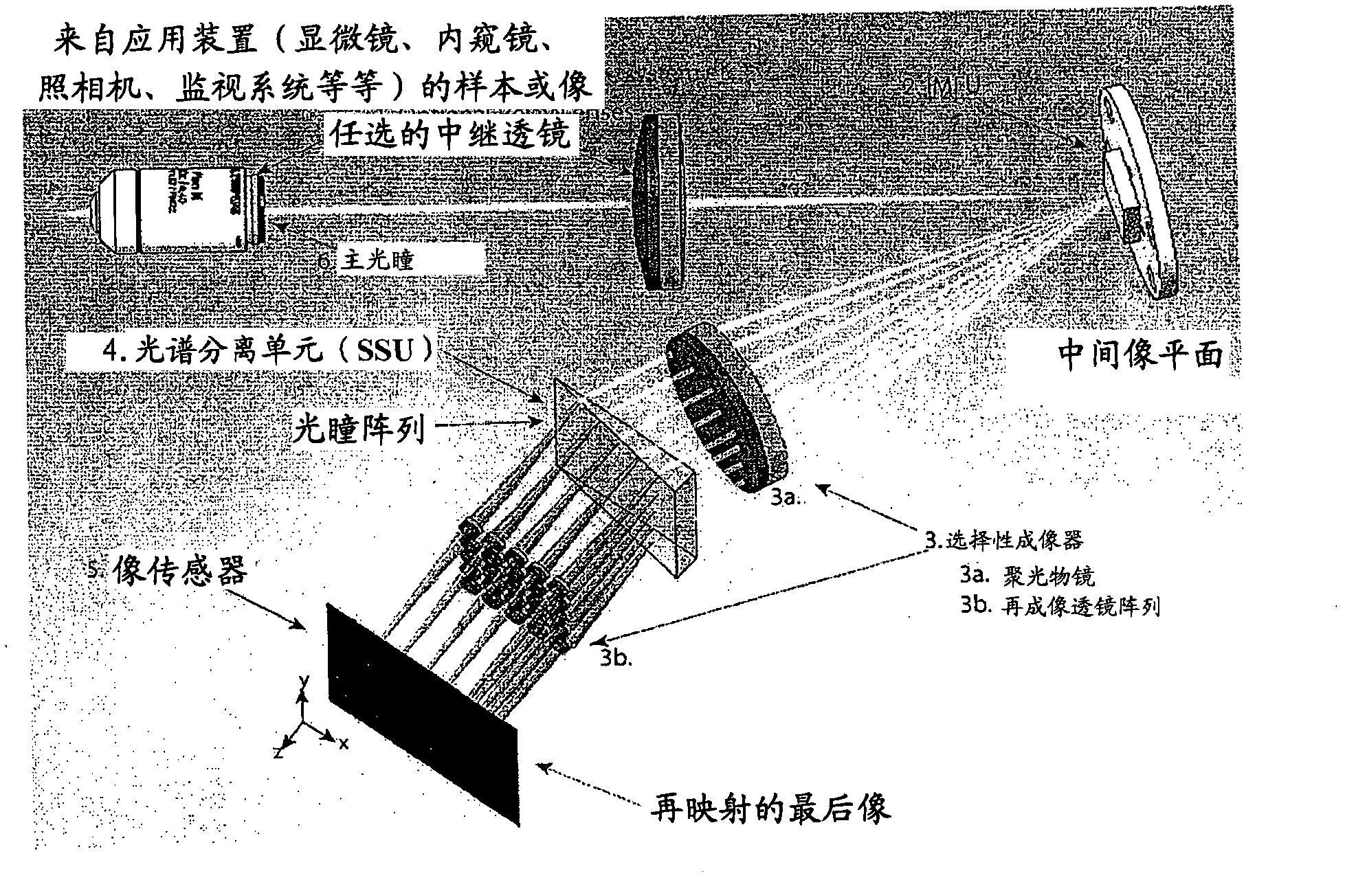
[0058] The present disclosure is generally in the field of hyperspectral and multispectral imaging. More particularly, the present disclosure relates to compact image mapping spectrometer ("IMS") systems and methods, according to certain embodiments.
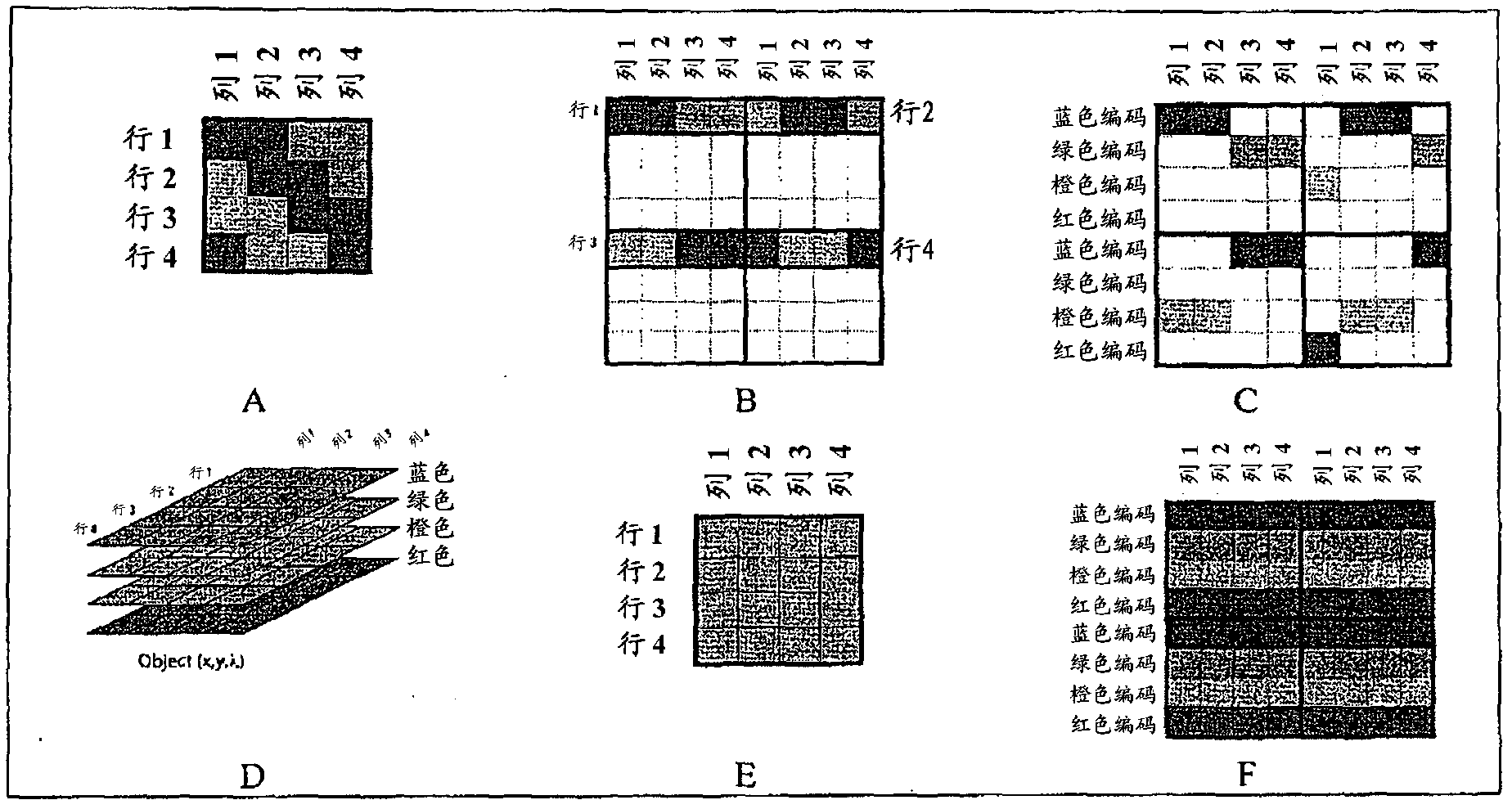
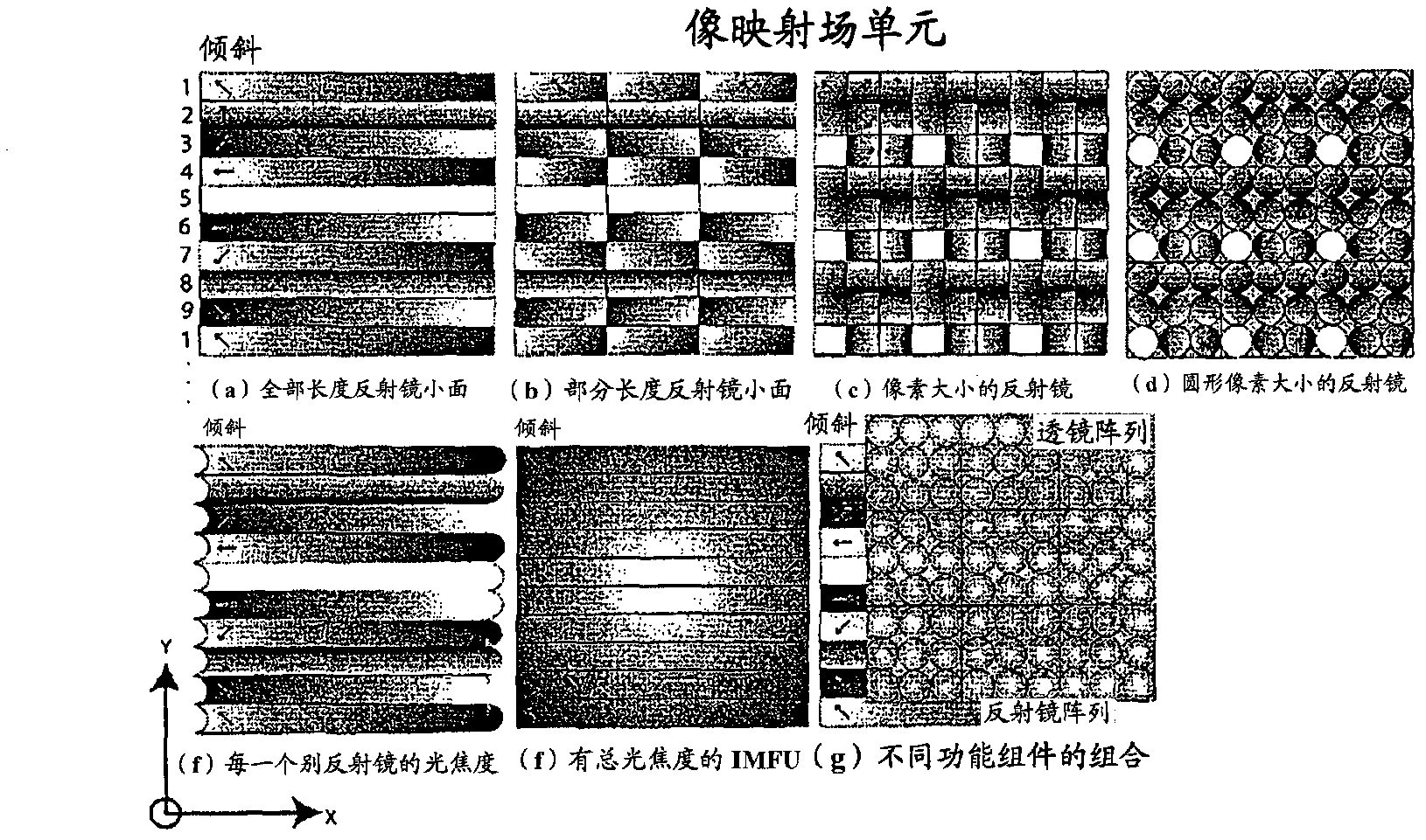
[0059] In the context of this document, the term "mapping" generally refers to the process by which data is transformed to form a final image. In a typical imaging system, the mapping transformation can be linear, often with axisymmetric. Mapping may also encompass any process that may pertain to a certain arrangement or orientation, thereby enabling spectral and spatial information to be collected in parallel.
[0060] As used herein, "lens" generally refers to any optical component or combination of multiple optical components having a combined optical power. A lens may include one or more refractive components, one or more diffractive components, one or more reflective components, and any combination of refractive, diffract...
PUM
 Abstract
Description
Claims
Application Information