Internal expansion fixture for thin-walled parts

An internal expansion and fixture technology, applied in the direction of expanding the mandrel, can solve the problems of controlling at about 0.1mm, the radial jump of the processed parts cannot be guaranteed, and the effective support force is not very large, so as to ensure the processing benchmark and improve the The effect of product quality

Inactive Publication Date: 2011-12-07
JIANGSU SAIC AUTOMOBILE SYNCHRONIZER WORKS
View PDF4 Cites 19 Cited by
  • Summary
  • Abstract
  • Description
  • Claims
  • Application Information

AI Technical Summary

Problems solved by technology

However, it has been found in actual use that since the elastic expansion sleeve 26 can rotate freely, and its elastic wall is quite thin, the effective supporting force is not very large, especially when the radial force generated when cutting grooves is relatively large, it will The radial jump of the processed parts is usually not guaranteed, and the general tolerance can only be controlled at about 0.1mm
In addition, there is also a disadvantage that this type of clamp is subjected to the pulling force F of the pull rod 28, such as image 3 As shown, when the tension F is converted into a radial expansion force f through the connecting rod 28 and the tapered surface 27 of the elastic expansion sleeve 26, the parts are only subjected to the tension force, while the positioning surface 25 of the parts and the fixture It is necessary to apply pressure to the positioning surface through the palm of the operator to ensure that one end of the part is closely attached to the positioning surface 25, so as to ensure the runout of the end face of the part. In this case, the runout is generally controlled at about 0.08mm
However, due to the addition of manual operations, it is easy to appear that the operator installs the parts at will and does not press the end face of the part on the positioning surface 25, resulting in a large machining error of the part.

Method used


Image

  • Internal expansion fixture for thin-walled parts
  • Internal expansion fixture for thin-walled parts
  • Internal expansion fixture for thin-walled parts

Examples


Embodiment Construction

[0012] In order to further reveal the technical solutions of the present invention, the implementation manners of the present invention will be described in detail in conjunction with the accompanying drawings.

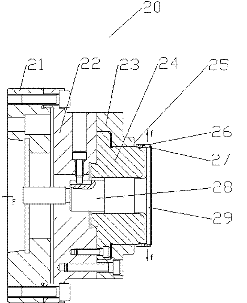
[0013] Please refer to Figure 4 , Figure 4 It is a schematic diagram of the overall structure of the internal expansion clamp for thin-walled parts of the present invention. The internal expansion clamp 30 in the figure includes: a machine tool connecting plate 31, which is used to fix the clamp to the machine tool; a pull rod flange 38, which passes through The connecting rod 32 on the periphery is connected with the elastic expansion sleeve 35; the positioning seat 33 is fixed on the connecting plate 31 of the machine tool as the shell of the fixture, and simultaneously plays a positioning role on the parts inside the fixture 30; the fixed mandrel 37, its It is fixed on the connecting plate 31 of the machine tool and the front end is a conical surface 36, and the...


PUM


Abstract

The invention discloses an internal expansion fixture for thin-walled parts. The fixture comprises: a machine tool connection plate, a tie rod flange plate, a positioning seat, and a fixed mandrel shaft. When the fixture disclosed by the present invention is in operation, under the action of the pull force of the pull rod of the machine tool, the pull force is transmitted to the elastic expansion sleeve through the pull rod flange and the connecting rod. Since the elastic expansion sleeve is limited by the connecting rod, it cannot rotate freely and can only move axially on the tapered surface of the fixed mandrel. At the same time, when the elastic expansion sleeve moves axially, it passes through the tapered surface of the fixed mandrel, and converts the pulling force into a radial expansion force and a pulling force toward the positioning surface. It is because of the above-mentioned pulling force toward the positioning surface that the parts will be automatically pressed against the positioning surface, and the parts will not be pressed tightly due to the operator's mistakes, resulting in gross errors in the processing of the parts. Therefore, the product quality of the parts is effectively improved, and the processing benchmark of the next process is guaranteed.

Description

technical field [0001] The invention relates to an internally expanding clamp, in particular to an internally expanding clamp for fixing thin-walled parts. Background technique [0002] With the continuous improvement of machining accuracy, the requirements for tooling and fixtures for parts processing are also getting higher and higher, especially for the processing of thin-walled cylindrical parts. The earliest internal three-jaw anti-expansion tooling fixture has basically been eliminated, such as figure 1 , the disadvantage of this fixture 10 is mainly that the stress points are on the three claws 11. After the processing is completed, due to the elastic deformation of the thin-walled parts, the roundness of the inner hole will be deformed so much that it cannot meet the product drawings at all. Require. [0003] Instead, the internal expansion fixture 20, such as figure 2 , it adopts the whole inner hole contact tensioning method. The fixture 20 is fixed to the mac...

Claims


Application Information

Patent Timeline
Patent Type & Authority Applications(China)
IPC IPC(8): B23B31/40
Inventor 王翼毛志明蒲惠军
Owner JIANGSU SAIC AUTOMOBILE SYNCHRONIZER WORKS
Why Eureka
Try Eureka