Screen printing method and device thereof

A screen printing device and screen printing technology, applied in the direction of screen printing machine, printing, printing machine, etc., can solve the problems of reducing filling and unevenness, etc.

Inactive Publication Date: 2011-12-07
HITACHI HIGH TECH INSTR CO LTD
View PDF10 Cites 7 Cited by
  • Summary
  • Abstract
  • Description
  • Claims
  • Application Information

AI Technical Summary

Problems solved by technology

If the angle of attack changes, the filling property to the opening of the printing mask will change, so the problem is to reduce the unevenness of the filling property

Method used


Image

  • Screen printing method and device thereof
  • Screen printing method and device thereof
  • Screen printing method and device thereof

Examples


Embodiment 1

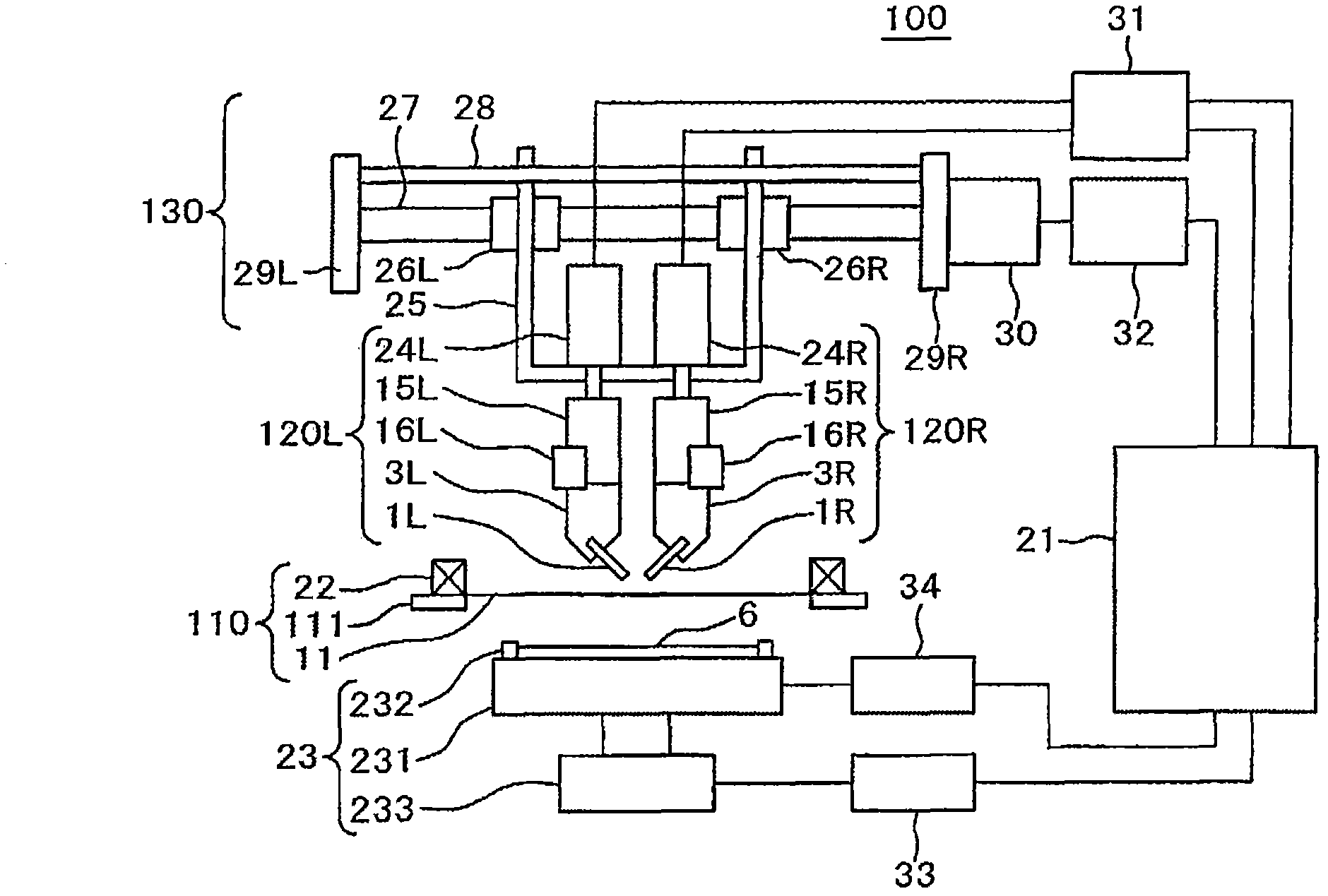
[0097] use figure 1 The configuration of the printing apparatus 100 of the first embodiment will be described. figure 1 It is a front view of the printing apparatus 100 of the first embodiment. For simplification purposes, figure 1 In , the representation of the frame, side walls, pillars, supporting members, etc. of the device is omitted.

[0098] The printing apparatus 100 has a printing mask unit 110 , a printed object support table unit 23 , a pair of squeegee units 120L and 120R, a squeegee drive mechanism unit 130 , and a control unit 21 .

[0099] The printing mask portion 110 is configured to have: a metal mask 11 provided with a pattern opening corresponding to a desired circuit pattern of the object to be printed (for example, a printed wiring board) 6; The frame 22, which is rectangular in plan view, is held in a tensioned state; and the supporting member 111 that supports the frame. The printed object supporting table unit 23 has a table 231 on which the printe...

Embodiment 2

[0146] This second embodiment is the same as the above-mentioned first embodiment except that a screen mask is used for the printing mask 11 .

[0147] In Embodiment 2, a mesh screen is used for the printing mask 11 . As the mesh, a #325 flat-woven mesh using a high-strength wire with a wire diameter of 16 μm and a yarn thickness of 35 μm was used. As this mesh, a mesh mask of pattern openings with a diameter of 50 μm to 200 μm formed by emulsions having a thickness of 35 μm and a thickness of 55 μm was used.

[0148] In order to release the printing mask 11 and the object 6 using the screen tension, the tension of the printing mask is 0.2 mm or less (measured with a tension gauge STG-80NA manufactured by PROTEK Corporation).

[0149] The metal mesh used for the printing mask 11 used in the second embodiment has an opening ratio of 40% or more, and the wire diameter for the metal mesh needs to be smaller than half of the opening width of the metal mesh.

[0150] In the patte...

Embodiment 3

[0160] use Figure 7 The structure of the squeegee mounted on the printing device of the third embodiment will be described. The squeegee used in Example 3 is a flat squeegee, and is a squeegee 71 in which a glass epoxy resin plate 727 is inserted into the center of the squeegee as a support.

[0161] A schematic diagram of the tip shape of the scraper 71 used in the third embodiment is as follows: Figure 8 shown. exist Figure 8 In the figure, in order to explain the shape of the tip of the squeegee 71, an enlarged view of the main part of the squeegee structure is shown by taking a flat squeegee as an example.

[0162] In the third embodiment, the installation direction of the squeegee 71 is set in the opposite direction to that of the first embodiment, and the squeegee 71 is inclined in the same direction as the printing direction 2 . Except that the shape of the scraper 71 is changed, it is the same as that of the first embodiment described above. Since the compositi...


PUM


Abstract

PROBLEM TO BE SOLVED: To provide a printing method and an apparatus for the printing method, in which a squeegee can be mounted, wherein the squeegee is shaped such that regardless of the size of the opening area of the opening of a printing mask, the rolling of paste is accelerated when paste is filled and transferred to a printing mask with a required pattern opening and the filling property of the paste into the pattern opening of the printing mask is also accelerated in order to achieve accurate and stable printing, in addition, force is applied vertically to the paste with respect to the opening of the printing mask.SOLUTION: In the printing apparatus, by using the squeegee, paste is transferred to a predetermined part of an object to be printed, which is fixed on a table, from the printing mask that has an opening in a predetermined position. In the printing apparatus, the corner of one of squeegee ends has an arcuate and concave shape. An attack angle between the squeegee and the printed side of the object to be printed is made to be smaller than the mounting angle of the squeegee. Accordingly, satisfactory printing can be achieved in the printing method and the apparatus for the printing method.

Description

technical field [0001] The present invention relates to a printing method and a device for screen printing a viscous printing material on an object to be printed by using a squeegee through a printing mask having a predetermined opening pattern. Background technique [0002] The so-called screen printing is a kind of stencil printing method. The paste (printing agent) such as ink is passed through a screen with an opening pattern by scraping (using a squeegee to push the paste (printing agent) out) so that the desired Patterns are transferred to printed objects, and screen printing is used in various applications such as circuit wiring formation on IC substrates and FDP (Flat Display Panel: Flat Display Panel) pattern formation (electrode formation and phosphor filling). [0003] Screen printing is also applied, for example, to printing of soft solder paste performed before actual mounting work of mounting electronic components on a printed wiring board. The solder paste is...

Claims


Application Information

Patent Timeline
Patent Type & Authority Applications(China)
IPC IPC(8): B41F15/44
CPCB41F15/08B41F15/14
Inventor 牛房信之西登小松龙一
Owner HITACHI HIGH TECH INSTR CO LTD
Why Eureka
Try Eureka