Low-retracting secondary stretch-draw anchorage supporting nut screwing device

A supporting nut and tensioning technology, applied in the erection/assembly of bridges, bridges, buildings, etc., can solve the problems of weakening the concrete structure size of bridges, difficult construction operations, and narrow space, and achieves improved construction efficiency, reduced operation difficulty, and reduced The effect of cutting the section

Inactive Publication Date: 2013-12-25
湘潭欧之姆预应力锚具有限公司
View PDF4 Cites 0 Cited by
  • Summary
  • Abstract
  • Description
  • Claims
  • Application Information

AI Technical Summary

Problems solved by technology

During the second tensioning construction of the anchor, the support nut needs to be tightened downwards. Because it is in the groove and the space is narrow, it brings difficulties and inconvenience to the construction operation. At the same time, in order to meet the manual tightening operation, the bridge deck The size of the reserved groove is larger, which weakens the structural size of the bridge concrete

Method used


Image

  • Low-retracting secondary stretch-draw anchorage supporting nut screwing device
  • Low-retracting secondary stretch-draw anchorage supporting nut screwing device
  • Low-retracting secondary stretch-draw anchorage supporting nut screwing device

Examples


Embodiment 1

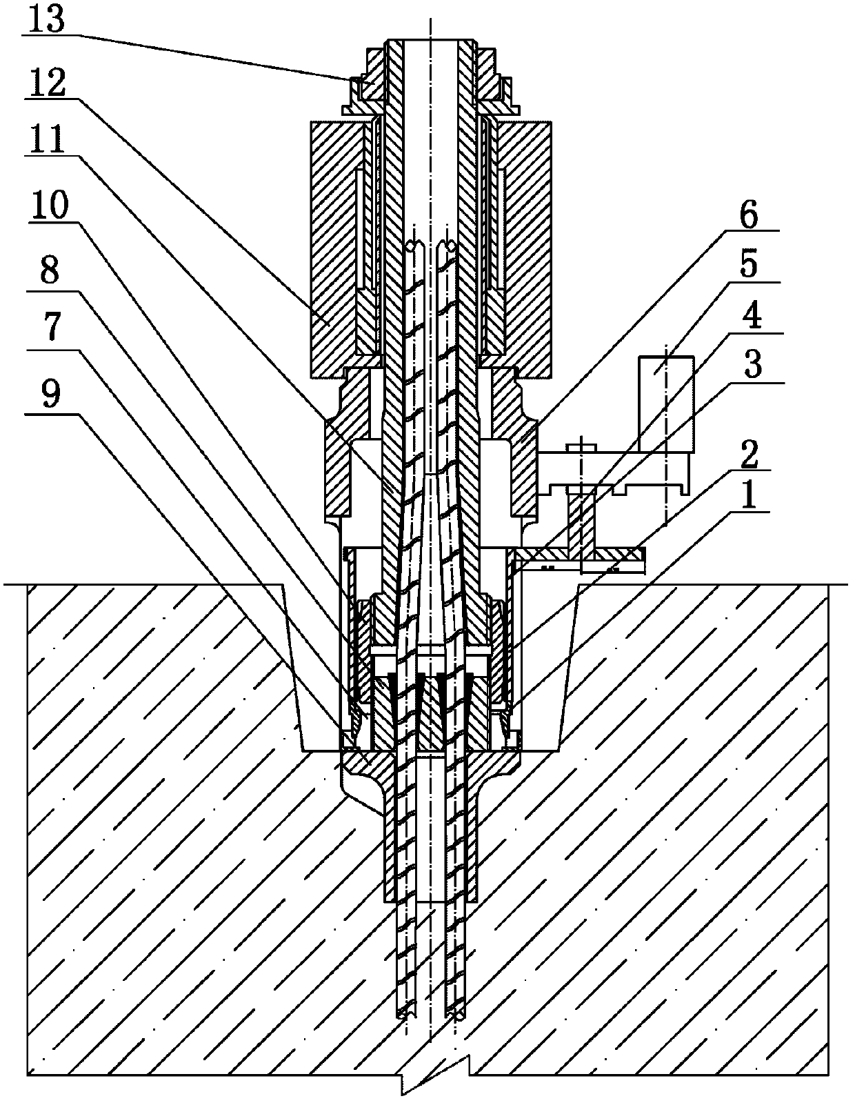
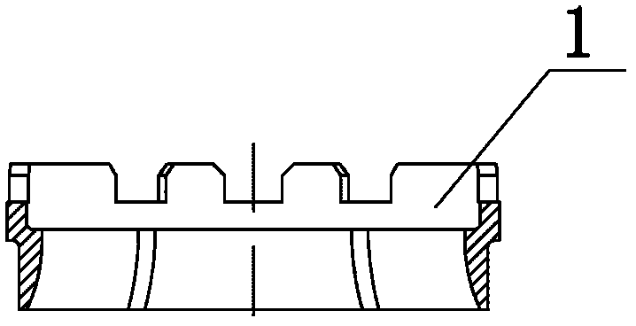
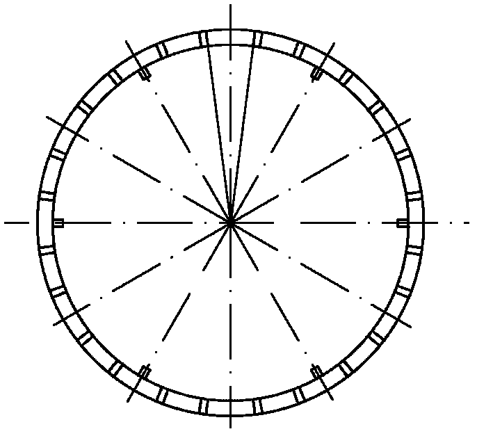
[0019] Example 1, see figure 1 , The present invention is mainly composed of the inner convex connecting sleeve 1, the transition sleeve 2, the passive rotating wheel 3, the active rotating wheel 4, the power machine 5 and the tension bracket 6, etc. The inner convex connecting sleeve 1 is sleeved in the secondary tension anchor On the support nut 7, one or more inner bosses can be designed in the inner cavity of the inner convex connecting sleeve 1. The inner bosses and the corresponding grooves on the outer periphery of the secondary tension anchor support nut 7 form a clearance fit. That is, the shape of the inner boss corresponds to the position of the outer circumferential groove of the support nut 7 and has the same shape, and the size of the inner boss is smaller than the groove size by 0.5-5 mm. Three or more grooves are provided on the upper end surface of the female-male connecting sleeve 1, and the lower end surface of the transition sleeve 2 is provided with three or...

Embodiment 2

[0020] Embodiment 2: The rotating device provided on the transition sleeve 2 of the present invention can also be a gear rotating mechanism. The upper end of the transition sleeve 2 is connected with the passive rotating wheel 3, and the passive rotating wheel 3 is connected with the manual rotating mechanism. When the secondary tension anchor completes the first tension and release, remove the jack and other tension tools, install the convex connecting sleeve 1 above the secondary tension anchor support nut 7, and install the tension connecting sleeve After 10 and the tension rod 11, the transition sleeve 2 and the passive rotating wheel 3 are installed on the outer periphery of the tension connection sleeve. At this time, there is a gap of 7-13 mm between the anchor ring 8 and the backing plate 9 for the second tension. At this time, the passive rotating wheel 3 can be driven by the manual rotating mechanism to drive the transition sleeve 2 to push the inner convex connecting ...

Embodiment 3

[0021] Embodiment 3: In addition to the manual operation mentioned above, the rotating device provided on the transition sleeve 2 of the present invention can also be driven by a power mechanism, see figure 1 , Connect the upper end of the transition sleeve 2 with the passive rotating wheel 3, and set a cylindrical gear on the outer periphery of the passive rotating wheel 3. The outer periphery of the driving rotating wheel 4 is set with a circular gear matched with the cylindrical gear on the outer periphery of the passive rotating wheel 3. The passive rotating wheel 3 The cylindrical gear on the outer circumference meshes with the circular gear on the outer circumference of the driving wheel 4 to transmit power; the center of the driving wheel 4 is designed with an inner shaft hole and a keyway and is connected to the output shaft of the power machine 5, which can be installed and fixed on the tension bracket On the side surface of 6, the shape and size of the tension support 6...


PUM


Abstract

The invention discloses a low-retracting secondary stretch-draw anchorage supporting nut screwing device which mainly aims to solve the technical problems that the existing low-retracting secondary stretch-draw anchorage supporting nut is inconvenient to screw and the like. The technical scheme is as follows: the device comprises an inward-convex connection sleeve (1), a transition sleeve (2), a driven rotary wheel (3), a driving rotary wheel (4), a power machine (5) and a stretch-draw bracket (6), wherein an inner boss is designed in the inner cavity of the inward-convex connection sleeve (1), and is matched with a groove corresponding to the periphery of a secondary stretch-draw anchorage supporting nut (7); more than three grooves are arranged at the upper end of the inward-convex connection sleeve (1); more than three bosses matched with the grooves at the upper end surface of the inward-convex connection sleeve (1) are arranged on the lower end surface of the transition sleeve (2); the grooves on the upper end surface of the inward-convex connection sleeve (1) are connected with the bosses on the lower end surface of the transition sleeve (2) in clearance fit; and a rotation device is arranged on the transition sleeve (2). The device disclosed by the invention well solves the problem of screwing the low-retracting secondary stretch-draw anchorage supporting nut, and can remarkably reduce the size of the reserved grooves on the bridge deck, reduce the concrete cut section of the bridge, reduce the difficulty in operating the knob supporting nut and improve the construction efficiency. The device can be widely applied to the box girder construction engineering adopting a suspension casting construction method, particularly to the mounting of the vertical pre-stressed low-retracting secondary stretch-draw anchorage in bridge engineering.

Description

Technical field [0001] The invention relates to a low-retraction secondary tension anchor supporting nut tightening device, in particular to a secondary tension anchor supporting nut tightening device in a groove. Background technique [0002] At present, low-retraction secondary tension anchors are used for vertical prestressing of bridge projects. Because the anchors are on the upper part of the beam but are not allowed to rise above the bridge deck, the low-retraction secondary tension anchors must be set below the bridge deck. In the groove. When the anchor is tensioned for the second time, the supporting nut needs to be tightened downwards. Because it is in the groove and the space is small, it brings difficulties and inconvenience to the construction operation. At the same time, to meet the manual tightening operation, the bridge deck The size of the reserved groove is larger, which weakens the structural size of the bridge concrete. Summary of the invention [0003] The o...

Claims


Application Information

Patent Timeline
Patent Type & Authority Patents(China)
IPC IPC(8): E01D21/00
Inventor 邵旭东万国强
Owner 湘潭欧之姆预应力锚具有限公司
Why Eureka
Try Eureka