Combined Serpentine Torque Wrench

A torque wrench, combined technology, applied in the direction of wrenches, screwdrivers, manufacturing tools, etc., can solve the problems of inconvenient disassembly and assembly, poor flexibility, limited torque of the built-in motor, etc., to achieve the effect of convenient disassembly and assembly, simple operation and accurate transmission

Inactive Publication Date: 2016-03-02
YANSHAN UNIV
View PDF7 Cites 0 Cited by
  • Summary
  • Abstract
  • Description
  • Claims
  • Application Information

AI Technical Summary

Problems solved by technology

[0003] Since the traditional torque wrench is generally a single straight rod structure, the torque rod cannot be bent, so it is extremely inconvenient to use when the space is limited and there are many obstacles.
And the wrench that can realize flexible torque transmission, such as: hydraulic torque wrench and pneumatic torque wrench, due to the need to match the corresponding power system, therefore, the whole wrench is relatively large and complicated, has poor flexibility, and is inconvenient to use; moreover, its head is generally small. There is a relatively large transmission device to complete the conversion of hydraulic energy or pneumatic energy to mechanical energy, which takes up a large space, so it is not convenient to complete disassembly and assembly work in a small space
[0004] The torque wrench described in the Chinese invention patent with the publication number CN1417002 is provided with a handle with an integrated built-in motor at the rear end of the straight hollow wrench, which can realize tightening or loosening the nut with a constant torque in a narrow space. However, It is not convenient to use in places with many obstacles; in addition, the torque of the built-in motor is limited, and it is impossible to complete high-torque work; and it is also impossible to achieve torque transmission at variable angles
The Chinese patent with the publication number CN1425536 discloses a pneumatic ratchet drive wrench. The wrench structure allows the head of the wrench to be smaller than the conventional pneumatic ratchet drive wrench, and it is easier to enter a small space. However, it still cannot get rid of the limitation of the volume of the air source. The wrench is still slightly bulky

Method used


Image

  • Combined Serpentine Torque Wrench
  • Combined Serpentine Torque Wrench
  • Combined Serpentine Torque Wrench

Examples


Embodiment Construction

[0028] specific implementation plan

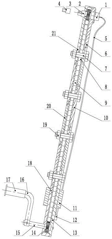
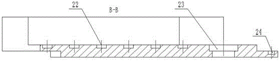
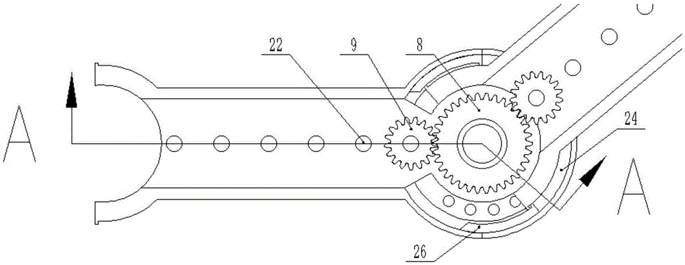
[0029] exist figure 1 In the schematic diagram of the combined serpentine torque wrench shown, the wrench mainly includes a torque input device, a torque output device and a torque transmission device. The torque transmission device is a plurality of coupling rods with the same structure, and each coupling rod includes: a pinion , connecting rod bottom groove and cover plate, central gear and studs, such as figure 2 , image 3 and Figure 4 As shown, one end of the groove bottom plate of the connecting rod bottom groove 20 is a circular plate, and the center of the circular plate is provided with a through hole 23, and five slotted holes 25 are respectively arranged symmetrically along the central plane of the circular plate, and the center lines of these slotted holes are at On a circle, be provided with the limit bead 28 in this groove, as Figure 5 As shown; the other end of the above-mentioned groove bottom plate is a concave arc-...


PUM


Abstract

The invention relates to a combined type snakelike torque spanner which mainly comprises a torque input device, a torque output device and torque transmission devices. The torque transmission devices are a plurality of linkage rods which are of the same structure. Each linkage rod comprises a small gear, a linkage rod bottom groove, a cover plate, a center large gear and a stud. The torque input device mainly comprises a tail rod, a tail rod bottom groove, a cover plate, a driving handle, a torque input gear, a small gear and a display screen. The torque output device mainly comprises an output rod, an output rod bottom groove, a cover, a torque sensor, a torque output gear, a torque output quadrangle screw, a replaceable work head and a data line. The combined type snakelike torque spanner has the advantages that operation is simple, the structure is light, the overall length and the angle are adjustable, a bolt can be tightly screwed under the condition that the space is confined, accurate torque transmission is achieved, and even if the shape of the spanner is changed, the transmission of torque cannot be affected.

Description

technical field [0001] The invention relates to an industrial assembly and maintenance tool, in particular to an assembly and maintenance wrench used for aerospace pipelines and other small nuts. Background technique [0002] With the development of large-scale aircraft, the number of aviation pipelines in a single aircraft has increased significantly, and because the pipeline system is very complex, the space limitations are large, such as the three-oil pipeline system on the aero-engine, and the pipelines in some space cabins. Road system, therefore, using traditional torque wrench, its installation is extremely inconvenient, and work efficiency is very low. At the same time, in general industry, if limited by space, there is also the problem that nuts, bolts, etc. are not easy to disassemble. This requires a torque wrench that can transmit torque conveniently and efficiently in a limited space to ensure the standardization and reliability of installation and improve work...

Claims


Application Information

Patent Timeline
Patent Type & Authority Patents(China)
IPC IPC(8): B25B23/00B25B23/142B25B13/48
CPCB25B13/481B25B23/00B25B23/142
Inventor 权凌霄郭长虹李东
Owner YANSHAN UNIV
Why Eureka
Try Eureka