
The electromagnetic valve

A solenoid valve and solenoid coil technology, applied in the field of solenoid valves, can solve the problems of high energy consumption and limited use of fluid regulating valves, and achieve the effects of reducing power consumption, reducing driving current, and avoiding mechanical failure and fatigue problems.

Inactive Publication Date: 2011-12-07
BEIJING AEONMED
View PDF4 Cites 14 Cited by
  • Summary
  • Abstract
  • Description
  • Claims
  • Application Information

AI Technical Summary

Problems solved by technology

Therefore, the energy consumption of the system is relatively high-
Especially for some applications controlled by batteries, the use of these fluid regulating valves is very limited

Method used


Image

  • The electromagnetic valve
  • The electromagnetic valve
  • The electromagnetic valve

Examples


Embodiment Construction

[0022] The embodiments of the present invention will be described in detail below in conjunction with the accompanying drawings, but the following embodiments and accompanying drawings are only used to understand the present invention, but not to limit the present invention. The present invention can be implemented in various ways defined and covered by the claims.

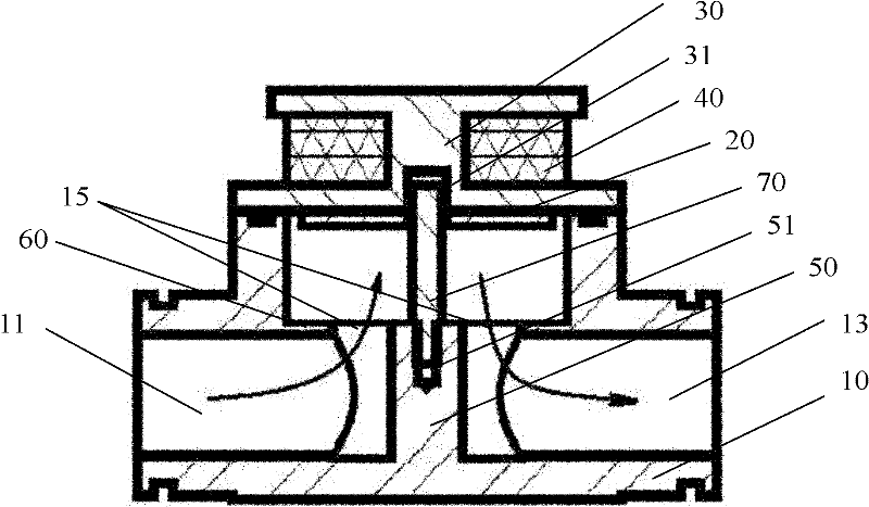
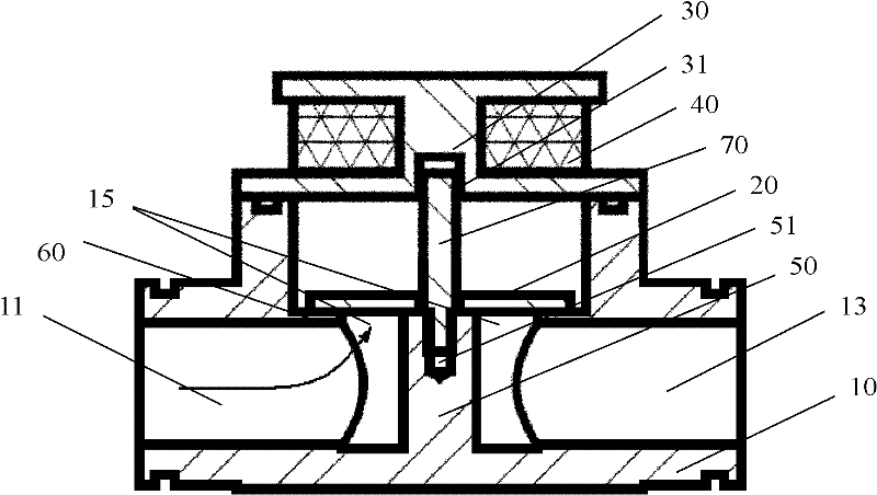
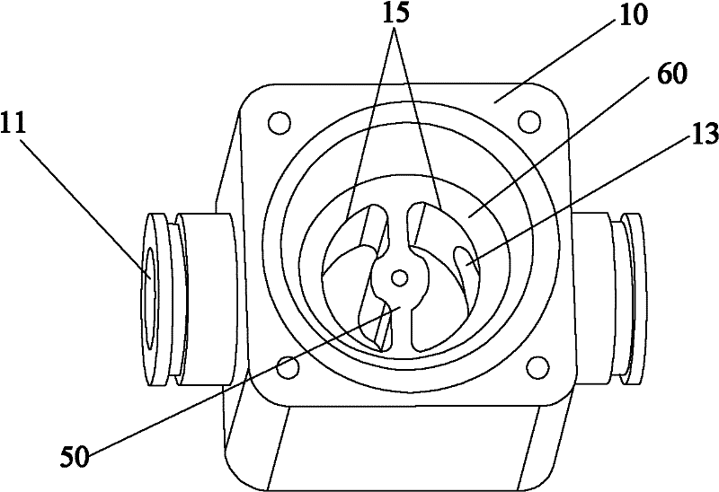
[0023] Such as figure 1 with figure 2 As shown, in a typical implementation of the present invention, the solenoid valve includes a valve seat 10, a valve core 20 and a valve cover 30, and the valve core 20 is movably arranged between the valve seat 10 and the valve cover 30 to form a In the inner cavity, at least one of the valve seat 10 or the valve cover 30 includes a magnetic material, and at least one is provided with an electromagnetic coil 40; the valve core 20 is a magnetized material. The solenoid valve applies electromagnetic force to the valve core through the electromagnetic field to drive the valve ...


PUM


Abstract

The invention discloses an electromagnetic valve which comprises a valve seat, a valve core and a valve cover, wherein the valve core can be movably arranged in an inner cavity formed between the valve seat and the valve cover, at least one of the valve seat or the valve cover comprises magnetic materials, and at least one of the valve seat or the valve cover is provided with an electromagnetic coil; and the valve core uses magnetic materials. The electromagnetic valve provided by the invention uses an electromagnetic force to combine with a static magnetic force so as to reset the valve core, thus the avoiding the problems of mechanical failure and fatigue probably existing in the reset operation of the valve core by mechanical parts such as a spring and the like; meanwhile, the valve core can be driven by the combination of electromagnetic force and static magnetic force to move, the response speed of the electromagnetic valve can be promoted relative to the movement of the valve core driven by the mechanical parts such as the spring and the like; besides, aiming at the application of lower pressure in a loop, the electromagnetic force and static magnetic force can be reasonablyconfigured on a basis of material and electromagnetic valve structure optimization, thus the drive current of the electromagnetic valve can be reduced and then the power consumption of the electromagnetic valve can be reduced; by designing a reasonable fluid pathway, the volume of the electromagnetic valve is far less than that of the electromagnetic valve of the same kind.

Description

technical field [0001] The invention relates to the mechanical field, in particular to an electromagnetic valve. Background technique [0002] At present, for some equipment that needs to control the flow rate of the fluid in the pipeline, an on-off valve or a flow regulating valve is generally installed. The on-off valve includes a valve seat, a valve cover, a valve core and an elastic reset part. The valve core and the elastic return part are arranged in the internal space formed by the connection between the valve cover and the valve seat. The valve core can move relative to the valve seat. There are two states of opening the spool and closing the spool. For a normally closed valve, the elastic reset piece presses on the spool in the opposite direction of opening the spool; for a normally open valve, the elastic return piece presses in the opposite direction of closing the spool. Press on the spool. The solenoid valve with such a structure will suffer from mechanical fa...

Claims


Application Information

Patent Timeline
Patent Type & Authority Applications(China)
IPC IPC(8): F16K31/06F16K1/42F16K1/36F16K27/12
Inventor 陈永辉
Owner BEIJING AEONMED
Learn More