Combustion Control Method of Regenerative Combustion Heat Treatment Furnace

A heat treatment furnace and regenerative combustion technology, applied in the combustion method, burner control device, burner and other directions, can solve the problems of unstable combustion, increase in fuel gas amount, and increase in the ratio of fuel gas to combustion air.

Inactive Publication Date: 2014-10-15
CHUGAI RO CO LTD
View PDF8 Cites 0 Cited by
  • Summary
  • Abstract
  • Description
  • Claims
  • Application Information

AI Technical Summary

Problems solved by technology

[0008] However, as mentioned above, a regenerative combustion type heat treatment furnace is provided with a plurality of pairs of regenerative burners, and in each pair of regenerative burners, the timing for switching between the combustion operation and the regenerative operation is different and will be constant. In the case of a regenerative combustion type heat treatment furnace in which a certain amount of fuel gas is supplied from the combustion gas supply device to each fuel gas supply pipe, in a pair of regenerative burners that switch between the combustion operation and the heat storage operation, temporarily stop as described above. The amount of fuel gas supplied via the fuel gas supply pipe increases the amount of fuel gas supplied from the fuel gas supply device to the fuel gas supply pipe of the other regenerative burner pair.
As a result, in other regenerative burner pairs, the ratio of fuel gas to combustion air increases, the combustion state changes, and there is a problem that proper combustion cannot be performed stably.
In particular, when a gas with poor combustibility, such as propane gas, is used as the above-mentioned fuel gas, if the ratio of propane gas to combustion air increases, black smoke (coal) will be generated due to incomplete combustion, which will cause environmental problems. There is also a problem that heat treatment cannot be properly performed due to coal adhered to the material to be treated

Method used


Image

  • Combustion Control Method of Regenerative Combustion Heat Treatment Furnace
  • Combustion Control Method of Regenerative Combustion Heat Treatment Furnace
  • Combustion Control Method of Regenerative Combustion Heat Treatment Furnace

Examples


Embodiment Construction

[0042] Hereinafter, the combustion control method of the regenerative combustion type heat treatment furnace concerning embodiment of this invention is demonstrated concretely based on drawing. In addition, the combustion control method of the regenerative combustion type heat treatment furnace of the present invention is not limited to the method shown in the following embodiments, and can be implemented with appropriate changes within the range not changing the gist of the invention.

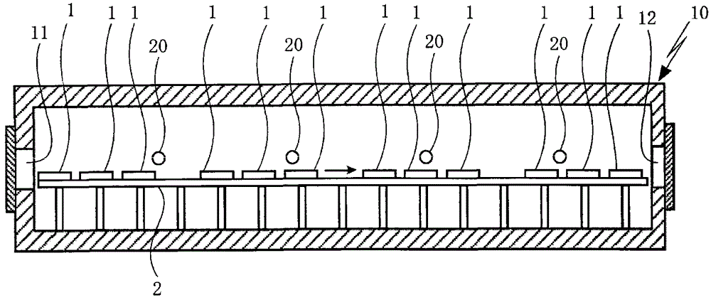
[0043] Here, in this embodiment, if figure 1 As shown, the material to be processed 1 made of steel that is guided from the inlet 11 of the regenerative combustion type heat treatment furnace 10 into the regenerative combustion type heat treatment furnace 10 is placed in the regenerative combustion type heat treatment furnace 10 by using a walking beam 2 It is transported, heat-treated, and the material 1 thus heat-treated is taken out of the heat-storage combustion-type heat treatment furnace...


PUM


Abstract

A combustion control method for a regenerative combustion type heat treatment furnace. When alternately switching the combustion operation and the heat storage operation in a pair of regenerative burners, the slave fuel gas supply pipe and the air supply pipe in each regenerative burner are The quantities of fuel gas and combustion air supplied from the tube are fixed, so that proper combustion can be performed stably. When switching between the combustion operation and the heat storage operation in a pair of regenerative burners (20), in the regenerative burner (20a) in combustion operation, the fuel gas supply pipe (28a) and the air supply The supply of fuel gas and combustion air supplied from the pipe (24a) decreases from the normal combustion state, and in the regenerative burner (20b) in the heat storage operation, the fuel gas supply pipe (28b) passes through the fuel gas supply pipe (28b) ) and air supply pipe (24b) to supply the fuel gas and combustion air supply from the stop state increased, and in a pair of regenerative burners, through the fuel gas supply pipe and the air supply pipe supplied from The supply of fuel gas and combustion air is fixed.

Description

[0001] related application [0002] This application claims the priority of Japanese Patent Application No. 2010-127569. technical field [0003] The present invention relates to a combustion control method of a regenerative combustion type heat treatment furnace. The regenerative combustion type heat treatment furnace is provided with at least one pair of regenerative burners. The pair of regenerative burners have: Combustion section; regenerator for storing heat storage material; air supply pipe for supplying combustion air to the regenerator; and waste gas discharge pipe for discharging combustion exhaust gas from the regenerator. In one regenerative burner, the combustion The air is guided from the air supply pipe to the combustion part through the regenerator, and the fuel gas is injected from the fuel gas supply pipe of the combustion part to carry out the combustion operation, while in the other regenerative burner, the combustion exhaust gas is led to the above-mention...

Claims


Application Information

Patent Timeline
Patent Type & Authority Patents(China)
IPC IPC(8): F27B9/40F27B9/36F23L15/00
CPCY02E20/34F23D14/22F23D14/66F23D2208/00F23L15/02F23N1/02
Inventor 木本康之幕谷秀人
Owner CHUGAI RO CO LTD
Why Eureka
Try Eureka