
Control device for internal combustion engine equipped with turbocharger

A technology of internal combustion engine and turbocharger, which is applied in the direction of engine control, internal combustion piston engine, combustion engine, etc., and can solve problems such as complex component structure and control

Inactive Publication Date: 2010-07-14
TOYOTA JIDOSHA KK
View PDF2 Cites 18 Cited by
  • Summary
  • Abstract
  • Description
  • Claims
  • Application Information

AI Technical Summary

Problems solved by technology

Furthermore, the hydraulic drive apparatus for valves described in JP-A-5-263671 is capable of performing stepless adjustment of the lift amount and operating angle of the first exhaust valve and the second exhaust valve, but has the The valve system with the function of continuously adjusting the lift amount requires complex component structures and controls.

Method used


Image

  • Control device for internal combustion engine equipped with turbocharger
  • Control device for internal combustion engine equipped with turbocharger
  • Control device for internal combustion engine equipped with turbocharger

Examples


Embodiment Construction

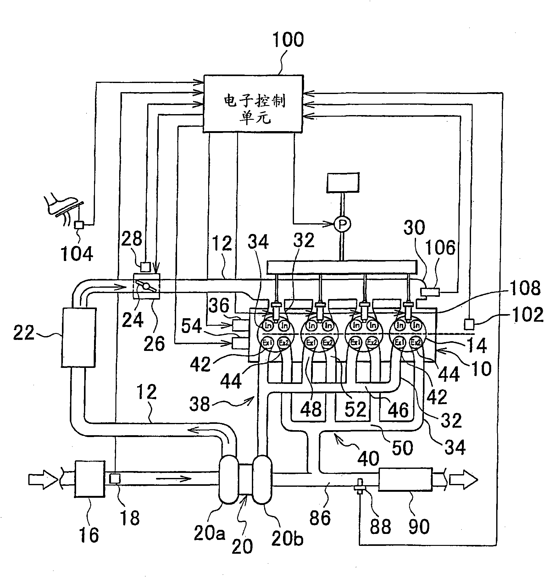
[0040] figure 1 The system configuration of the first embodiment of the present invention is shown. figure 1 The system shown includes an internal combustion engine 10 having four cylinders.

[0041] The intake system of the internal combustion engine 10 has an intake passage 12. Air is drawn from the atmosphere into the intake passage 12 and distributed among the combustion chambers 14 of each cylinder. The air cleaner 16 is installed at the inlet of the intake passage 12. An air flow meter (AFM) 18 is provided in the vicinity of the downstream area of ​​the air cleaner 16, and the air flow meter 18 outputs a signal corresponding to the flow rate of air sucked into the intake passage 12.

[0042] The turbocharger 20 is provided downstream of the air flow meter 18. The turbocharger 20 has a centrifugal compressor 20a and a turbine 20b. An intercooler 22 for cooling compressed air is provided downstream of the compressor 20a. The throttle valve 24 is provided downstream of the i...


PUM


Abstract

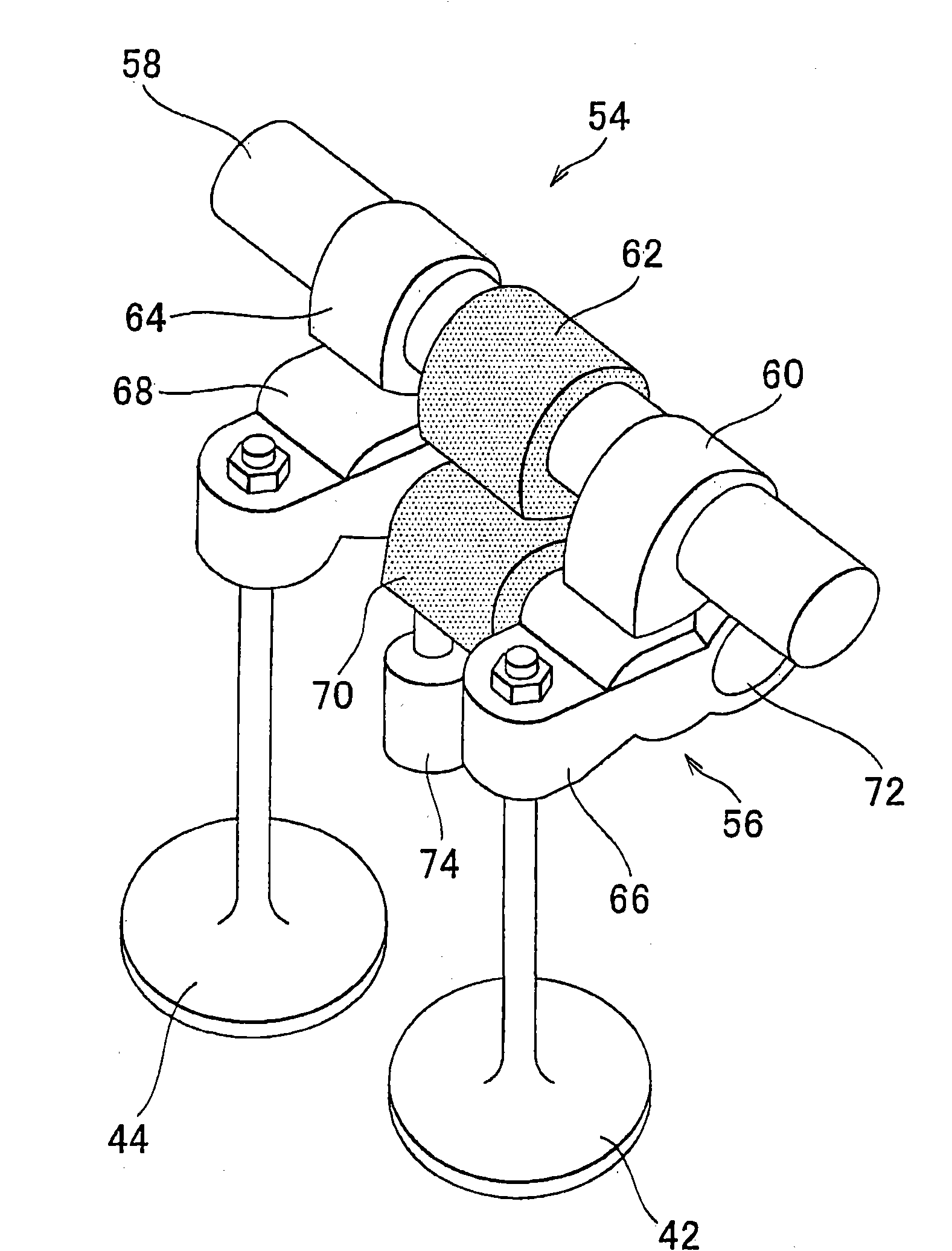
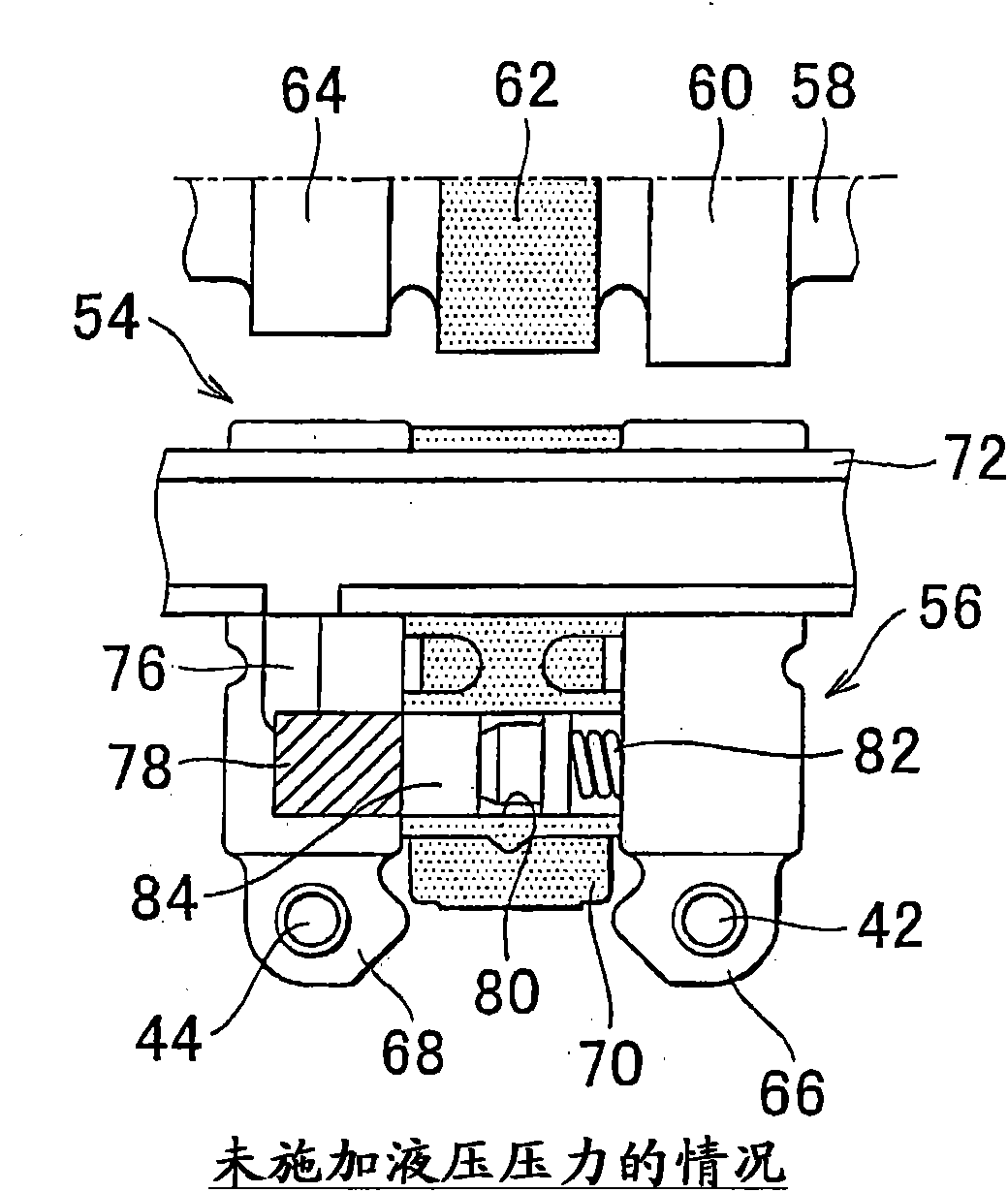
A control device for an internal combustion engine equipped with a turbocharger has a first exhaust channel (38) leading to a turbine (20b) of the turbocharger (20), a second exhaust channel (40) that does not lead to the turbine (20b), a first exhaust valve (42) that opens and closes the first exhaust channel (38), a second exhaust valve (44) that opens and closes the second exhaust channel (40), and an exhaust variable valve mechanism (54) that has a medium cam (62) and a small cam (64) as cams that drive the second exhaust valve (44) and can change a lift amount and a working angle of the second exhaust valve (44) by switching the cam profiles. The adjustment of the amount of exhaust energy supplied to the turbine (20b) and the adjustment of the turbine revolution speed and superchargepressure are performed by switching the cam profiles of the second exhaust valve (44).

Description

Technical field [0001] The invention relates to a control device for an internal combustion engine equipped with a turbocharger. Background technique [0002] For example, Japanese Patent Application Publication No. 10-89106 (JP-A-10-89106) describes an internal combustion engine equipped with a turbocharger. The internal combustion engine has a first exhaust valve that opens and closes a first exhaust passage leading to the turbine, and a second exhaust valve that opens and closes a second exhaust passage that does not lead to the turbine. In this internal combustion engine, in the high-speed region, the first exhaust valve is opened before the end of the expansion stroke and the second exhaust valve is opened in the first half of the exhaust stroke. In addition, the internal combustion engine has a wastegate valve for controlling the supercharging pressure and the turbine speed in the passage bypassing the turbine of the turbocharger. [0003] For example, Japanese Patent Appli...

Claims


Application Information

Patent Timeline
Patent Type & Authority Applications(China)
IPC IPC(8): F02D13/02F02D23/00
CPCF01L2800/08F02D41/0007F02D2041/001F01L1/20Y02T10/144F01L1/185F01L13/0036F01L1/267F02D13/0246F02D13/0257Y02T10/18F02B37/18F02D41/008F02B29/0406F01L13/0005F01L2001/186Y02T10/12
Inventor 宫下茂树
Owner TOYOTA JIDOSHA KK
Learn More