
Constant-current constant-voltage pulse charger that can set charging voltage and charging current arbitrarily

A technology of charging current and charging voltage, which is applied in the field of constant current and constant voltage pulse chargers, can solve the problems of difficult activation of active substances, decreased storage capacity of batteries, and easy burning of chargers, etc., so as to achieve good charging effect and reduce harmful The effect of gas emission and convenient operation

Inactive Publication Date: 2011-12-07
何庆余
View PDF6 Cites 10 Cited by
  • Summary
  • Abstract
  • Description
  • Claims
  • Application Information

AI Technical Summary

Problems solved by technology

Ordinary chargers are charged with full-wave or half-wave rectified pulsating current, or charged after rectified by a high-frequency transformer, which is equivalent to DC charging. Charging with such a current is not easy to activate the active material on the battery plate, and it will also cause The storage capacity of batteries continues to decline
There is also a charger that uses a thyristor as a charging element, which belongs to pulse charging. Pulse charging is easy to activate active substances, but since constant current and constant voltage charging cannot be performed, someone must be on duty, otherwise it will cause overcharging or insufficient charging. When the charging current is too large, It is also easy to burn the charger or damage the battery

Method used


Image

  • Constant-current constant-voltage pulse charger that can set charging voltage and charging current arbitrarily
  • Constant-current constant-voltage pulse charger that can set charging voltage and charging current arbitrarily
  • Constant-current constant-voltage pulse charger that can set charging voltage and charging current arbitrarily

Examples


Embodiment Construction

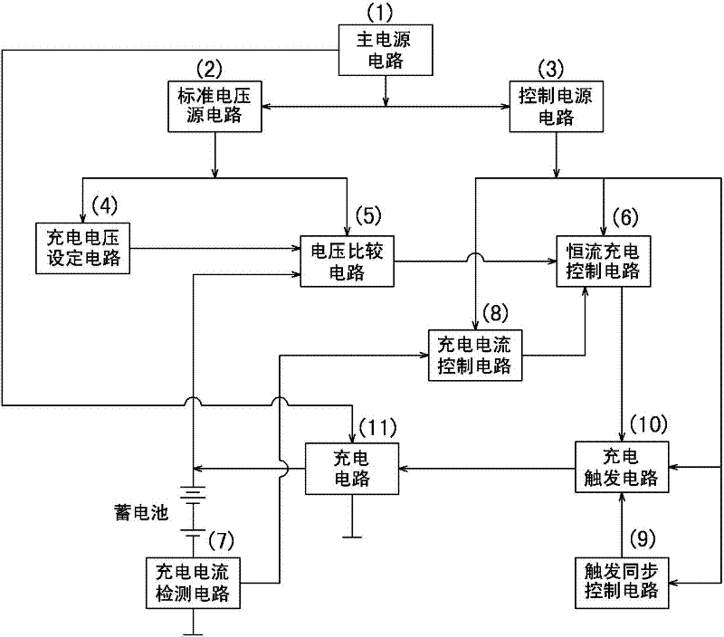
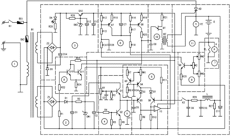
[0019] Such as figure 1 , figure 2 As shown, it includes main power supply circuit 1, standard voltage source circuit 2, control power supply circuit 3, charging voltage setting circuit 4, voltage comparison circuit 5, constant current charging control circuit 6, charging current detection circuit 7, charging current control circuit 8. Trigger synchronous control circuit 9, charging trigger circuit 10 and charging circuit 11, main power circuit 1 is connected with standard voltage source circuit 2, control power circuit 3 and charging circuit 11 to provide power for each circuit, standard voltage source circuit 2 respectively It is connected with the charging voltage setting circuit 4 and the voltage comparison circuit 5 to provide working power for each circuit, and the control power supply circuit 3 is respectively connected with the constant current charging control circuit 6, the charging current control circuit 8, the trigger synchronization control circuit 9 and the ch...


PUM


Abstract

The invention discloses a constant-current constant-voltage pulse charger capable of randomly setting charging voltages and charging currents. The pulse charger comprises a main power supply circuit (1), a standard voltage source circuit (2), a control power supply circuit (3), a charging voltage setting circuit (4), a voltage comparison circuit (5), a constant-current charging control circuit (6), a charging current detection circuit (7), a charging current control circuit (8), a triggering synchronous control circuit (9), a charging trigger circuit (10) and a charging circuit (11). The pulse charger works in an unattended mode, has a good protective effect on storage batteries and can prolong service life of storage batteries. The pulse charger has the advantages of low manufacturing cost, good charging effect and long service life. The constant charging voltage and constant charging current of the pulse charger are randomly set, so as to achieve non-polar pulse charging effects, prevent over-charging of storage batteries, and ensure that storage batteries are full. The pulse charger works without needing to be monitored, and practices prove that the performances of the pulse charger are sable and reliable.

Description

technical field [0001] The invention relates to a charger, in particular to a constant current and constant voltage pulse charger. Background technique [0002] When charging lead-acid batteries with common chargers currently available on the market, personnel need to be supervised. If the care is not done properly, the chargers will burn out, animal batteries will be undercharged or overcharged, etc., which will reduce the storage capacity of the batteries and even be scrapped. Although there are self-control chargers on the market, its self-control effect is not ideal, and the situation of charging and scrapping batteries often occurs, and its service life is also relatively short. Although there are also constant-current and constant-voltage chargers on the market, they are mainly used in large-scale charging units and are controlled by microcomputers. The cost is relatively high, and they are not suitable for ordinary users. [0003] Most of the chargers sold in the mar...

Claims


Application Information

Patent Timeline
Patent Type & Authority Applications(China)
IPC IPC(8): H02J7/04H02J7/10
Inventor 何庆余何智生
Owner 何庆余
Learn More