Winding machine and winding method

A winding method and a technology of winding dies, which are applied in the direction of electromechanical devices, manufacturing motor generators, electrical components, etc., can solve problems such as inability to wind wires, disorderly winding, and wire entry

Active Publication Date: 2011-12-07
NITTOKU ENG CO LTD
View PDF8 Cites 5 Cited by
  • Summary
  • Abstract
  • Description
  • Claims
  • Application Information

AI Technical Summary

Problems solved by technology

Therefore, the wire stretched radially outward by the side winding die may enter the gap between the top of the central winding die and the magnetic pole, and the wire cannot be wound in the part where the wire is originally intended to be wound.
Therefore, in the conventional flying fork type winding device with a central winding die and side winding dies, in the process of winding the wires to the magnetic poles, there may be disorder in the neat winding of the wires, so there is room for improvement.

Method used


Image

  • Winding machine and winding method
  • Winding machine and winding method
  • Winding machine and winding method

Examples


Embodiment Construction

[0037] Hereinafter, the best mode for carrying out the present invention will be described based on the drawings.

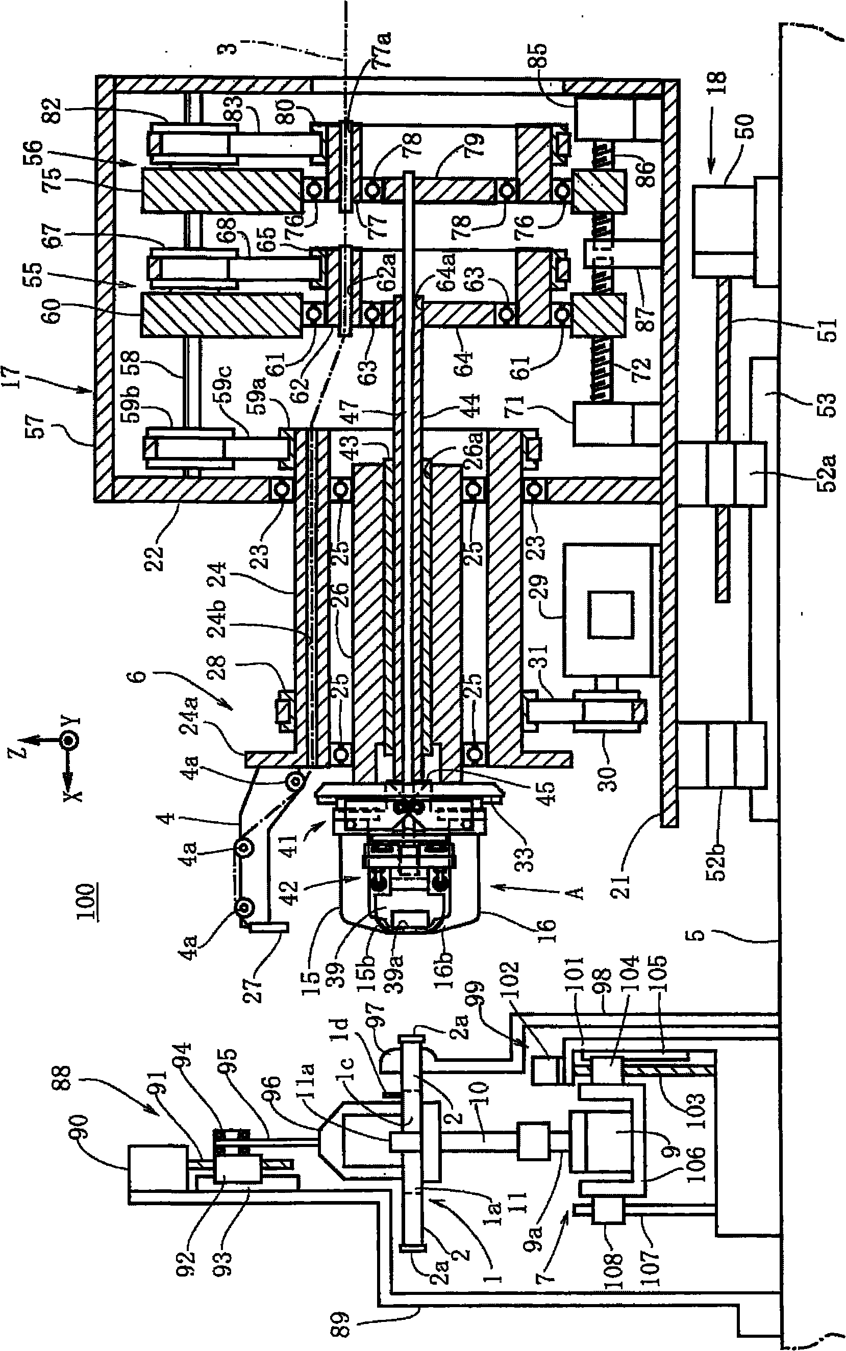
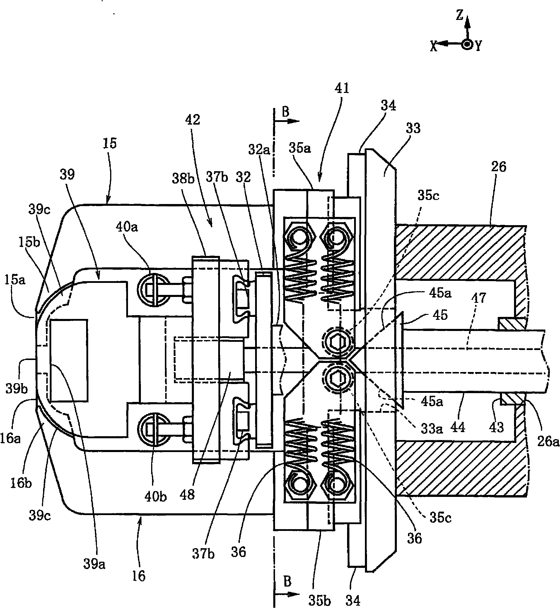
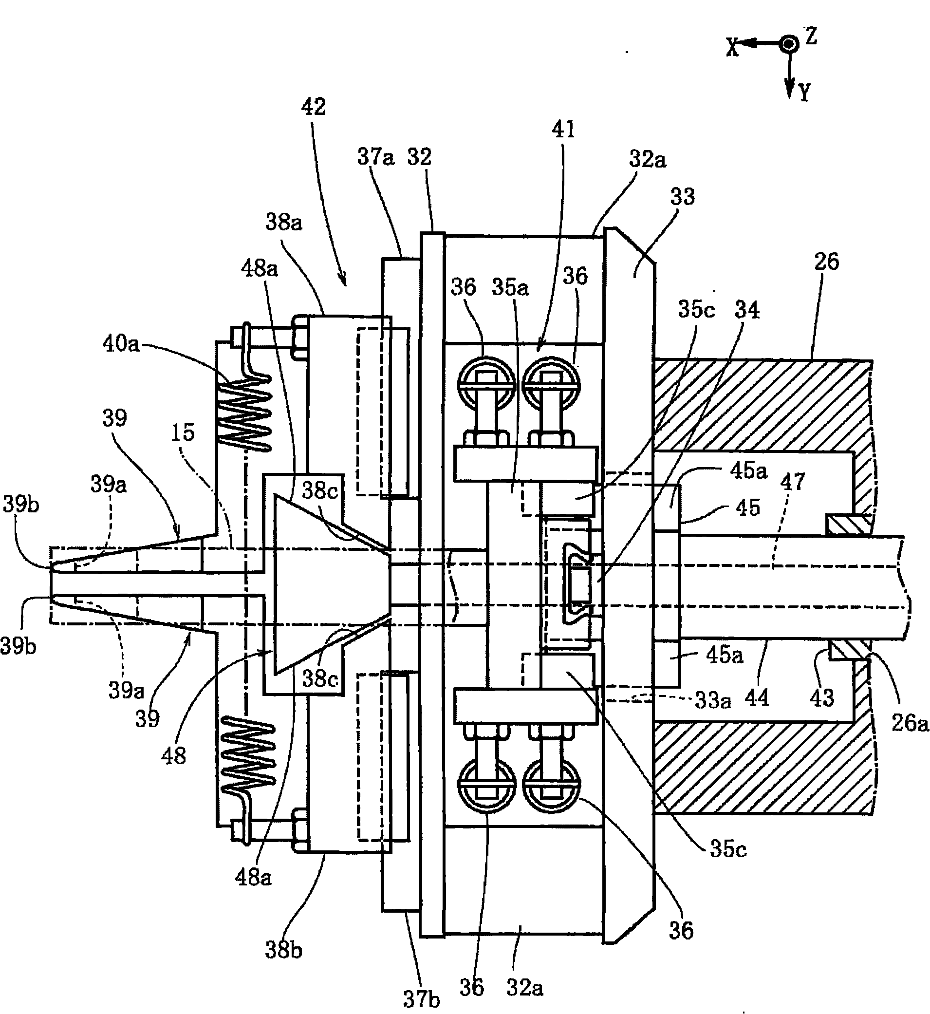
[0038] figure 1 Shows the winding device 100 of the present invention. The winding device 100 is a device that winds a multi-layer wire 3 around a plurality of magnetic poles 2 of a multi-pole armature 1 (stator) that constitutes an engine or a motor. It uses a flying wire that rotates around the magnetic pole 2 while leading out the wire 3 A flying fork type winding device for winding the fork 4. The multipole armature 1 in this embodiment is an armature including a ring portion 1a and 18 magnetic poles 2 projecting radially outward from the ring portion 1a ( Image 6 Middle represents 7 magnetic poles). Such as Image 6 As shown, an opening is formed between the magnetic poles 2 of the multi-pole armature 1 to form a slot 1b. The cross section of the magnetic pole 2 is quadrangular, and the outer peripheral surface of the magnetic pole 2 is composed of four smoo...


PUM


Abstract

The invention provides a coil winding device and a coil winding method, wherein coils can be stably and evenly wound on a multi-polar armature even with multiple poles. The coil winding device comprises a flying fork for winding coils on a pole; a pair of central winding dies for guiding coils derived from the flying fork to the pole; a first movement mechanism for moving the pair of central winding dies in a mutually separated or approached manner; a pair of side plates arranged to clamp the pole from the circumferential direction of the multi-polar armature. The top edges of side plates are in the same plane with the top edge of the central winding dies. Along with the rotation of the flying fork, the side plates move toward the radial direction of the multi-polar armature together with the central winding dies; and a second movement mechanism for moving the pair of side plates in the circumferential direction of the multi-polar armature in a mutually separated or approached manner. The side plates are formed with openings. A flange part formed on the protruding end of the pole can enter the opening so as to form a covering part for covering the side edge of the side plates on the central winding dies.

Description

Technical field [0001] The present invention mainly relates to a winding machine and a winding method for winding a wire for forming a coil on a multi-pole armature. Background technique [0002] In the past, in order to wind a wire for forming a coil on the magnetic poles of a multi-pole armature, a flying fork type winding machine with a flying fork is widely used. The flying fork rotates around the magnetic pole while drawing out the wire, and winding the magnetic pole Wire. In addition, in order to achieve better performance with the limited size of armatures such as motors, it is required how the winding machine can perform more windings in the limited winding space of the multi-pole armature. In this regard, an effective method is to neatly wind the magnetic poles of adjacent wires without gaps, that is, so-called neatly winding. Therefore, the following flying fork winding machine is known, which includes a pair of central winding dies, which are clamped and wound from t...

Claims


Application Information

Patent Timeline
Patent Type & Authority Applications(China)
IPC IPC(8): H02K15/095
Inventor 酒井勉
Owner NITTOKU ENG CO LTD
Why Eureka
Try Eureka