
flow regulator

A technology of flow regulators and regulators, which is applied in flow control, control/regulation systems, instruments, etc., can solve the problems of installing flow regulators, etc., and achieve the effect of simple cost and favorable processing

Active Publication Date: 2011-12-07
NEOPERL
View PDF2 Cites 8 Cited by
  • Summary
  • Abstract
  • Description
  • Claims
  • Application Information

AI Technical Summary

Problems solved by technology

Since the clamping edge area and the rubber seals provided on both sides require considerable space, the known flow regulator cannot always be retrofitted

Method used


Image

  • flow regulator
  • flow regulator
  • flow regulator

Examples


Embodiment Construction

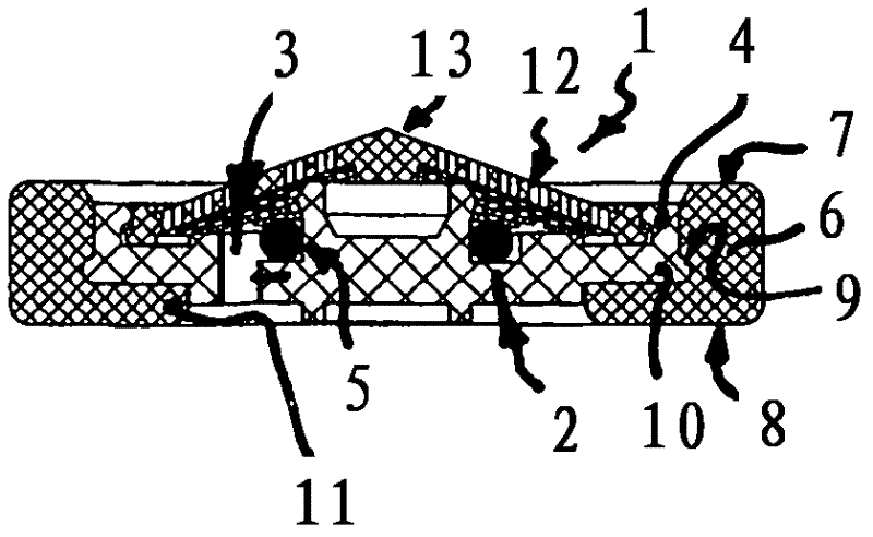
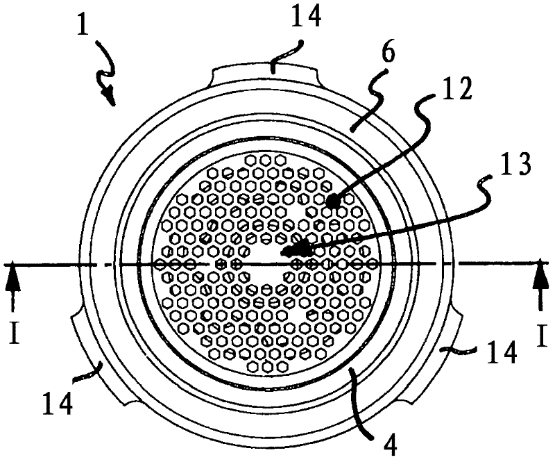
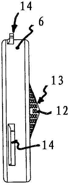
[0055] exist Figures 1 to 6 , 8 to 33 and 35 show flow regulators 1, 30, 31, 32 and 33, which have an annular throttling body 2 made of elastically deformable material, which is arranged in the regulating In the flow channel 3 of the device housing 4. The throttle body 2 delimits a control gap 5 between itself and an adjustment contour provided on the channel wall on the inner or outer circumference side, which in its inner flow cross-section is due to the flow medium The throttle body 2 deformable under pressure is variable. Because the throttle body 2 made of elastically deformable material deforms under the pressure of the incoming water and because the control gap 5 thus narrows with increasing incoming water pressure, the unit of medium passing through the throughflow channel 3 can be reduced. The throughput of time is determined at the maximum value.

[0056] as in Figures 1 to 6 , 8 to 33 and 35, the regulator housing 4 of the flow regulators 1, 30, 31, 32 and 33 ...


PUM


Abstract

The invention relates to a flow quantity regulator (1) having at least one throttle body (2) made of elastically deformable material, disposed in the permeating channel (3) of a regulator housing (4) and delimiting a control gap (5) between the same and a control profile disposed on an inner and / or outer circumferential channel wall, said control gap (5) being changeable in the open flow cross section thereof, due to the throttle body (2) that can deform under the pressure of the permeating meidum, wherein the regulator housing (4) comprises a clamping edge area for clamping the flow quantity regulator (1) between two line segments or line components connected to each other. The flow quantity regulator (1) according to the invention is characterized in that the regulator housing (4) is disposed in the ring opening of a sealing ring (6) and that upstream and downstream face areas (7, 8) of the sealing ring (6) form the clamping edge area. The flow quantity regulator (1) according to the invention can easily be installed in a plumbing supply line, even under tight space conditions, wherein the sealing ring (6) provided as the clamping edge area of the regulator housing (4) externally seals off the end faces, facing each other, of the line segments to be connected to each other.

Description

technical field [0001] The invention relates to a flow regulator with at least one throttle body made of an elastically deformable material, which is arranged in a throughflow channel of the regulator housing and between it and the inner circumference Between the adjustment contours arranged on the channel walls on the side and / or on the outer circumference side, a control gap is defined, which is variable in its inner flow cross-section due to a throttle body deformed under the pressure of the flow medium, wherein On the outer peripheral side, the regulator housing has a clamping edge region for clamping the flow regulator between interconnected pipe sections or pipe parts. Background technique [0002] Flow regulators are used for installation in sanitary water pipes in order to set the quantity of water drawn from this water pipe to a maximum value independently of the water pressure. Such flow regulators are already known in different embodiments. [0003] Flow regulat...

Claims


Application Information

Patent Timeline
Patent Type & Authority Applications(China)
IPC IPC(8): E03C1/086
CPCE03C1/086B05B1/18B05B1/3006G05D7/012Y10T137/1624Y10T137/7857Y10T137/7879E03C1/08
Inventor F·维尔德方
Owner NEOPERL
Learn More