An Improved Structure of Feed Distributor for Decanter Centrifuge

A decanter centrifuge and improved structure technology, applied in centrifuges and other directions, can solve the problems of inconvenience and inconvenience of on-site replacement, and achieve the effects of small space, convenient maintenance and cost reduction.

Active Publication Date: 2011-12-14
SHANGHAI CENTRIFUGE INST
View PDF5 Cites 4 Cited by
  • Summary
  • Abstract
  • Description
  • Claims
  • Application Information

AI Technical Summary

Problems solved by technology

Therefore, the replacement is very inconvenient, and it cannot be replaced on site. It must be ret

Method used


Image

  • An Improved Structure of Feed Distributor for Decanter Centrifuge
  • An Improved Structure of Feed Distributor for Decanter Centrifuge
  • An Improved Structure of Feed Distributor for Decanter Centrifuge

Examples


Embodiment Construction

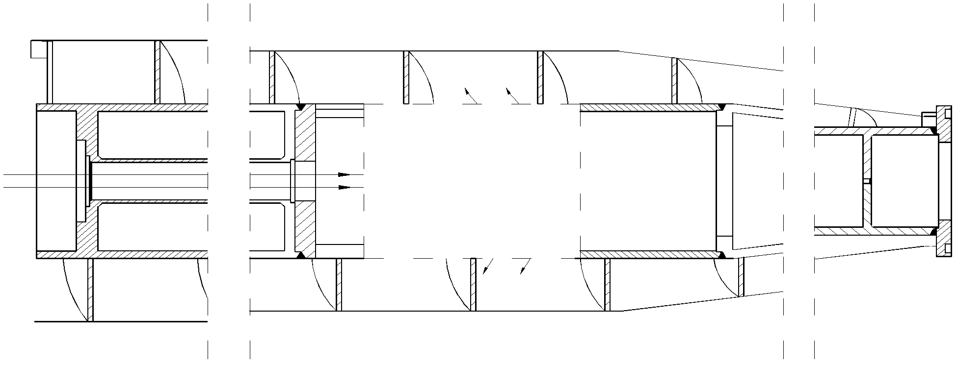
[0039] The present invention will be further described below in conjunction with the accompanying drawings, where the direction of the arrow in the figure is the flow direction of the floc material.

[0040] figure 1 The position of the dotted box in the middle is the assembly position of the feed distributor in the decanter centrifuge. The floc material enters from the left end of the feed distributor and is discharged from the upper and lower outlets.

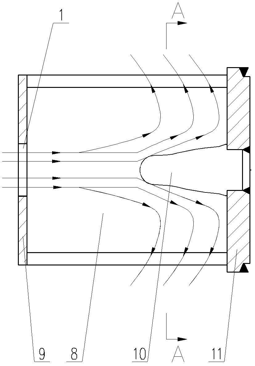
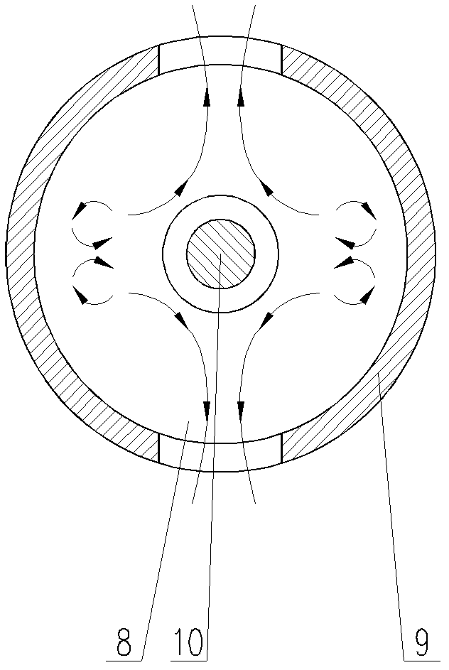
[0041] Figure 2~3 Among them, the horizontal drum body 9 has a circular distribution cavity 8 inside, the right end of the barrel body 9 is an open end, covering the end cover 11, the left end is a closed end, and a feed hole 1 is opened in the center to communicate with the distribution cavity 8 , The top and bottom of barrel body 9 are vertically provided with discharge ports, which communicate with distribution chamber 8. The right end of the distribution chamber 8 is equipped with a distributor head 10 facing the feed ...


PUM


Abstract

An improved structure of the feed distributor of a decanter centrifuge. A rectangular feed distribution chamber is vertically set up along the axis of a horizontally placed solid cylinder body. The right end of the cylinder is a closed end, and a feed hole is set at the axis of the left end. , the right end of the feed distribution chamber is equipped with a feed distribution head, the feed distribution head is an arc-shaped oblique wedge with upper and lower symmetry, the head is facing the feed hole, and the longitudinal section along its center line is sinusoidal. The left end of the transverse section of the center line is tongue-shaped, and the right end is rectangular. It is fixed in the feed distribution cavity of the cylinder body. The improved feed distributor can provide a relatively large flow area and a soothing flow channel for the floc material, which protects the integrity of the floc material and slows the wear of the feed distribution head; the distributor can be replaced on site It does not need to be transported back to the manufacturer for repair welding, which is convenient for maintenance.

Description

technical field [0001] The present invention relates to decanter centrifuges and more particularly to feed distributors. Background technique [0002] The basic working principle of the horizontal screw centrifuge is: after the material enters the machine drum from the feeding pipe in the center of the hollow screw conveyor, the liquid with low density is distributed on the outer wall of the screw conveyor to form a liquid ring, and the liquid with high density The solid slag is settled on the inner wall of the drum under the action of centrifugal force. The screw conveyor continuously pushes the solid slag from the cylindrical part of the drum to the conical part through the spiral structure, and is discharged from the equipment. [0003] The screw conveyor is the core component of the decanter centrifuge, which has a decisive influence on the performance and separation effect of the whole machine. At the same time, some parts of the spiral are also the parts that are mos...

Claims


Application Information

Patent Timeline
IPC IPC(8): B04B11/06
Inventor 钱青钱健航卢彦俊周成蹊
Owner SHANGHAI CENTRIFUGE INST
Why Eureka
Try Eureka