Sludge resource treatment device and method for treating sludge

A processing device and resource-based technology, applied in dewatering/drying/concentrating sludge treatment, combustion methods, incinerators, etc., can solve the problems of increasing processing time and cost, increasing the cost of drying raw materials, increasing the amount of exhaust gas, etc., and achieving savings Drying energy, ensure drying effect, energy saving effect

Active Publication Date: 2011-12-14
陈海渊
View PDF9 Cites 47 Cited by
  • Summary
  • Abstract
  • Description
  • Claims
  • Application Information

AI Technical Summary

Benefits of technology

This patented technical solution involves providing an apparatus called a filtrating tank used in treatments on sewage or industrial wastes. It has pits made up of filters covering its borders and pools filled with filtering materials like sand or gravel to remove any remaining liquid before disposal. When this material becomes saturated due to excess moisture content inside them, it falls down through holes onto another layer where other solid matter can be separated based upon their size. Dryers then separate these solids from liquor while still warm enough to prevent clump formation. These techniques help save power when processing large amounts of dirty fluid at once.

Problems solved by technology

This technical problem addressed in these documents relates to the development of effective techniques for efficiently handling and utilizing excessive amounts of municipal wastes generated during production processes like civil engineering projects. Current solutions involve expensive and energy intensive physical facilities, leading to environmental concerns. There have been attempts made towards developing new ways to effectively dispose of various types of residues produced throughout industry practice without causing negative impacts upon their surroundings.

Method used


Image

  • Sludge resource treatment device and method for treating sludge
  • Sludge resource treatment device and method for treating sludge

Examples


Embodiment 1)

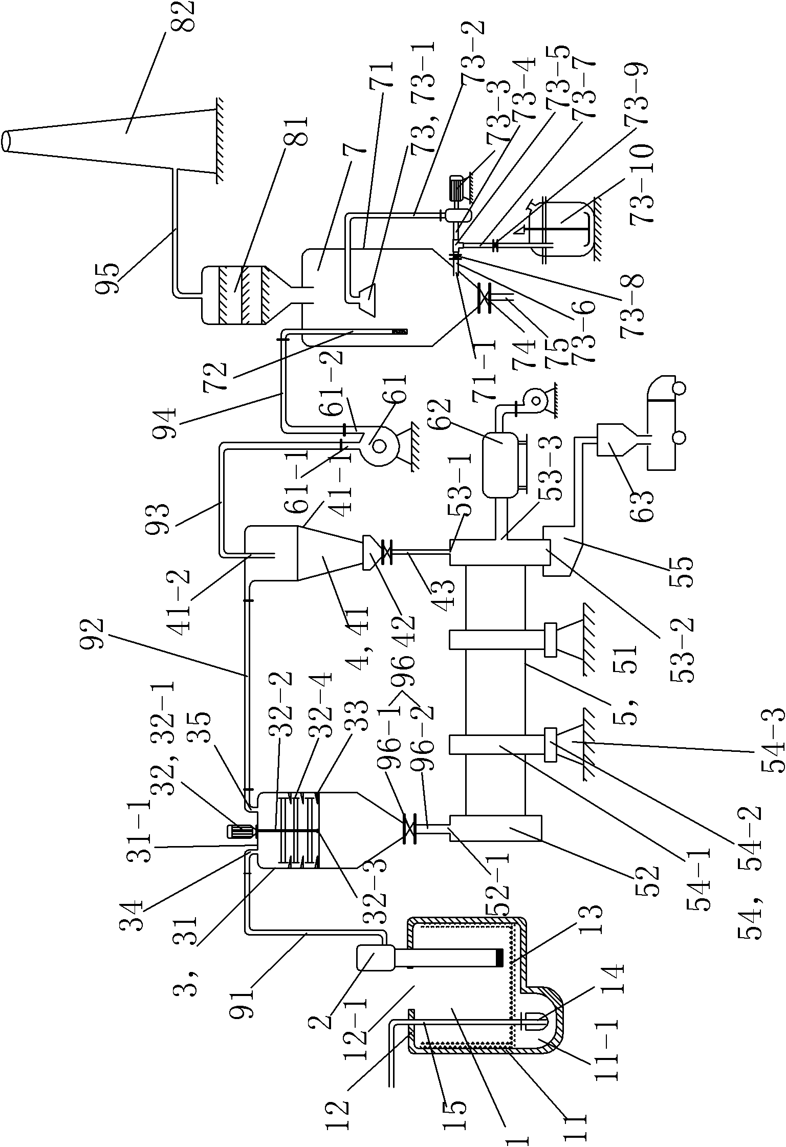
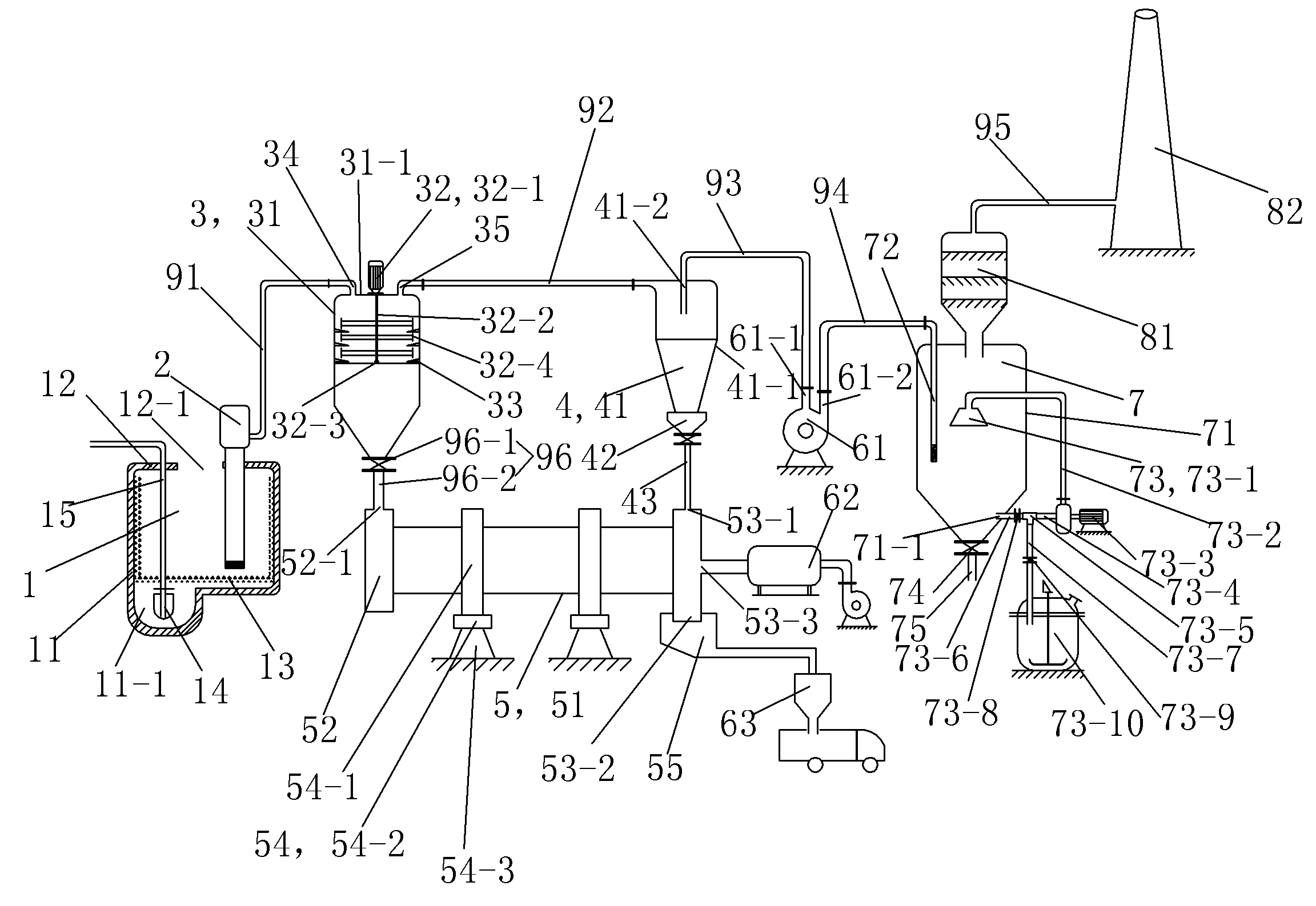
[0053] See figure 1 The sludge resource treatment device in this embodiment includes a filter tank 1, a sludge conveying device 2, a waste heat drying tower 3, a cyclone separation device 4, a rotary kiln 5, an induced draft fan 61, a hot blast stove 62, a collection tank 63, Deodorization tower 7, gas-liquid separator 81 and chimney 82. The sludge conveying device 2, the waste heat drying tower 3, the cyclone separation device 4, the induced draft fan 61 and the deodorizing tower 7 are connected through pipelines in sequence. The discharge port of the waste heat drying tower 3 and the discharge port of the cyclone separation device 4 are respectively connected with corresponding ports of the rotary kiln 5 .

[0054] The filter pool 1 includes a pool body 11 , an upper cover plate 12 , a filter screen 13 , a submerged pump 14 and an outlet pipe 15 . The side of the pool bottom of the pool body 11 is provided with a pit 11-1 sunken downward, and the submerged pump 14 is place...


PUM


Abstract

The invention discloses a sludge resource treatment apparatus and a sludge treatment method using the same. The apparatus comprises a collecting filter, a sludge conveying device, a waste heat drying column, a cyclone separator, a rotary kiln, a draught fan, an airheater, a gathering tank, a deodorizing tower, a gas-liquid separator and a chimney, wherein the sludge conveying device, the waste heat drying column, the cyclone separator, the draught fan, and the deodorizing tower are successively connected through pipelines. When the sludge is anhydrated by the sludge resource treatment apparatus, the sludge generated by a sewage treatment plant is treated with gravity settlement to filter free water, dried with waste heat from the rotary kiln in the waste heat drying column and enters intothe rotary kiln to realize drying or sintering of the sludge; stink, flue gas and water vapor generate during the process is guided into the deodorizing tower for treatment by the draught fan. The treatment apparatus of the present invention has a compact and stable structure, small land occupation, is convenient for maintenance, and can be prepared into container overlap to facilitate carrying and save space.

Description


Claims


Application Information

Patent Timeline
Owner 陈海渊
Why Eureka
Try Eureka