Shearing unit with humidity control

A shearing device and humidity control technology, applied in the field of auxiliary equipment, can solve the problems of unable to meet the humidity requirements of the cloth, complex structure, and inability to use a wide range of cutting operations, etc., to achieve neat cutting, lower temperature of the cutter head, and high-speed cutting Effect

Inactive Publication Date: 2011-12-14
许同永
View PDF8 Cites 1 Cited by
  • Summary
  • Abstract
  • Description
  • Claims
  • Application Information

AI Technical Summary

Problems solved by technology

The structure of this trimming device is too complex to use a large range of cutting operations
Equally, this cutting machine also can't meet the humidity requirement of different cloths that need cutting

Method used


Image

  • Shearing unit with humidity control
  • Shearing unit with humidity control
  • Shearing unit with humidity control

Examples


Embodiment Construction

[0019] The preferred embodiments of the present invention will be described in detail below in conjunction with the accompanying drawings, so that the advantages and features of the present invention can be more easily understood by those skilled in the art, so as to define the protection scope of the present invention more clearly.

[0020] The invention provides a shearing device that can be installed on various looms, has a simple structure and high cutting efficiency.

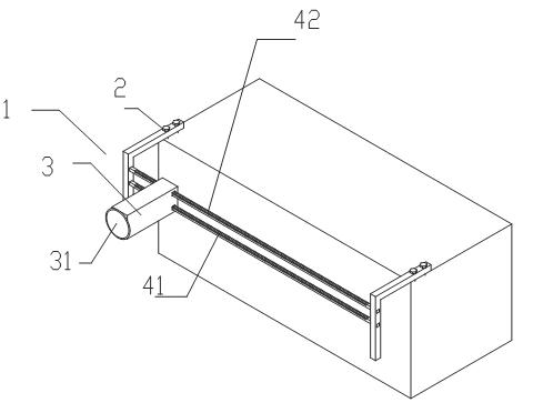
[0021] Such as figure 1 As shown, the shearing device 1 for the loom of the present invention includes a fixed bracket 2 and a cutter head 3 . The fixed bracket 2 is provided with a main slide rail 41 and an auxiliary slide rail 42,

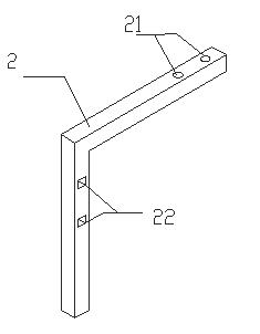
[0022] Such as figure 2 As shown, the fixed bracket 2 includes a shearing device installation hole 21 and a slide rail installation hole 22, and the fixed bracket 2 is L-shaped.

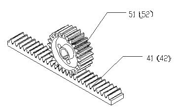
[0023] Such as image 3 As shown, a main gear 51 and an auxiliary gear 52 are arranged insid...


PUM


Abstract

The invention discloses a shearing device with a humidity control device. The shearing device includes a fixed bracket and a cutter head. The cutter head includes a disc blade. The cutter head also includes a Atomizing nozzles for the local ambient humidity of the disc blades described above. The fixed bracket is provided with a main slide rail and an auxiliary slide rail, the inside of the cutter head is provided with a main gear and an auxiliary gear, the main gear is meshed with the main slide rail, and the auxiliary gear is Engage with the auxiliary slide rail described above. The cutter head also includes a humidity sensor. The shearing device for the loom of the present invention utilizes the double slide rail design of the main slide rail and the auxiliary slide rail, which greatly increases the stability of the cutter head and realizes high-speed cutting of the cloth. At the same time, the cutting device utilizes controllable fog The spray head can provide a suitable humidity environment for the cloth to be cut, and at the same time can reduce the temperature of the blade head, making the cutting more neat.

Description

technical field [0001] The invention relates to an auxiliary equipment of a loom, more precisely, a shearing device with a humidity control device for a weaving machine. Background technique [0002] Need to utilize cutter to cut cloth after the cloth weaving on textile machine is finished, and generally adopt manual cutting or adopt special-purpose shearing device to cut cloth at present. [0003] Chinese invention patent ZL01224056.7 discloses a loom cutting machine, which includes: a sliding bar arranged on the frame of the loom; a control seat slidably arranged on the sliding bar, the An extension rod is extended on one side of the control seat; a cutter is arranged at the end of the extension rod of the control seat, and the cutter includes a motor and a cutting knife driven by the motor. This cutting machine only includes an extension rod, which has poor stability. When cutting cloth, the whole cutter head is prone to shaking. Simultaneously, this cutting machine di...

Claims


Application Information

Patent Timeline
Patent Type & Authority Applications(China)
IPC IPC(8): D06H7/00
Inventor 许同永
Owner 许同永
Why Eureka
Try Eureka