Internal leakage insert snap-in end face seal safety valve for electric water heater

A technology for end face sealing and electric water heaters, which is applied in the direction of multi-way valves, valve devices, engine components, etc., can solve the problems of low assembly efficiency, complicated production process, and difficult quality assurance, and achieve both stability and economy, and improve Effects of Reliability and Manufacturing Cost Reduction

Active Publication Date: 2011-12-14
浙江豪路热能科技有限公司
View PDF6 Cites 3 Cited by
  • Summary
  • Abstract
  • Description
  • Claims
  • Application Information

AI Technical Summary

Problems solved by technology

However, its internal leakage structure uses a copper insert with a boss to connect the safety valve through threads. Due to the complicated production process of the copper internal leakage insert with a boss, there are problems such as difficult quality assurance, heavy weight, and high cost. , In addition, the copper insert and the safety valve are connected by threads, the assembly method is inefficient, and there may be hidden dangers such as improper installation

Method used


Image

  • Internal leakage insert snap-in end face seal safety valve for electric water heater
  • Internal leakage insert snap-in end face seal safety valve for electric water heater
  • Internal leakage insert snap-in end face seal safety valve for electric water heater

Examples


Embodiment 1

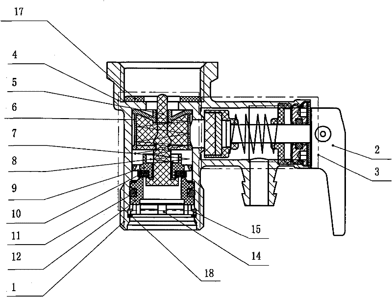
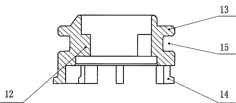
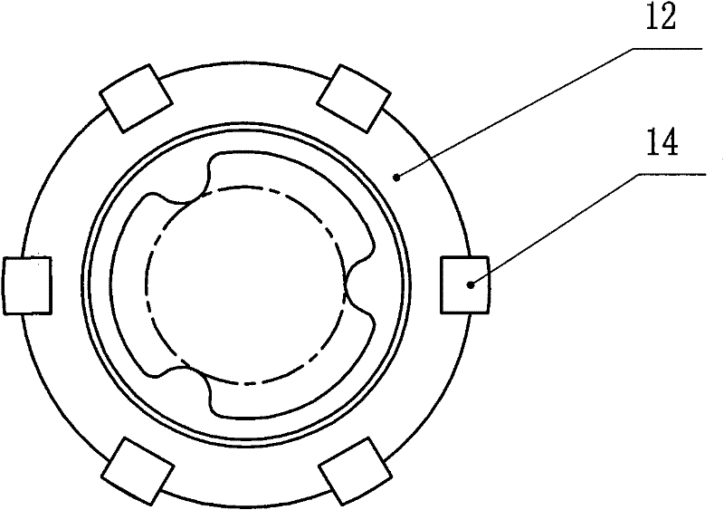
[0013] Embodiment 1: as figure 1 As shown, the internal leakage insert snap-in type end face seal electric water heater safety valve includes valve body 1, handle 2, external leakage body 3, internal leakage body 4 and flat gasket 17, internal leakage body 4 includes valve stem 5, with Filter card seat 6, water inlet spring 7, pressure spring 8, spring seat 9, reverse sealing gasket 10, O-ring 11 and internal leakage insert 12, such as figure 2 and image 3 As shown, the internal leakage insert 12 includes a reverse sealing seat 13 and a positioning foot 14, the positioning foot 14 is set under the reverse sealing seat 13, an O-ring groove 15 is provided on the reverse sealing seat 13, and the reverse sealing seat 13 Cooperate with the inner ring of the valve body 1, the O-ring 11 is set in the O-ring groove 15, and a groove 16 is provided under the reverse sealing seat 13 in the valve body 1, and the positioning foot 14 is snapped into the groove 16 for positioning. The nu...

Embodiment 2

[0014] Embodiment 2: as figure 1 As shown, the internal leakage insert snap-in type end face seal electric water heater safety valve also includes a circlip 18, the circlip 18 snaps into the groove 16, and is located under the positioning pin 14, and the number of positioning pins 14 is 60 , and evenly distributed below the reverse seal seat 13, the reverse seal seat 13 on the internal leakage insert 12 is integrated with the positioning foot 14, and its material is high-strength engineering plastics, such as polyoxymethylene, and the rest are the same as in embodiment 1.

Embodiment 3

[0015] Embodiment 3: The number of positioning feet 14 is 28, and they are evenly distributed under the reverse sealing seat 13, and the rest are the same as Embodiment 1 or Embodiment 2.


PUM


Abstract

The invention discloses an internal leakage insert snap-in end face seal electrical water heater safety valve which comprises a valve body, a handle, an external leakage body, an internal leakage body and a flat gasket, wherein the internal leakage body comprises a valve rod, a clamping seat with a filter screen, a water inlet spring, a pressure spring, a spring seat, a negative sealing gasket, an O-shaped ring and an internal leakage insert; the internal leakage insert comprises a negative sealing seat and a positioning pin, the positioning pin is arranged below the negative sealing seat, anO-shaped ring grove is arranged on the negative sealing seat, the negative sealing seat is matched with an inner ring of the valve body, an O-shaped ring is arranged in the O-shaped ring groove, a groove is arranged below the negative sealing seat in the valve body, and the positioning pin is clamped in the groove. The internal leakage insert snap-in end face seal electrical water heater safety valve has the characteristics of reliable quality, light weight, low cost, convenience for installation, and the like.

Description

technical field [0001] The invention relates to a safety valve for an electric water heater, in particular to a safety valve for an electric water heater with end face sealing. Background technique [0002] The existing electric water heater safety valve has partly adopted the end face sealing structure. When the safety valve of this structure is connected with the water heater, it is sealed by a flat gasket, and the sealing effect is better. However, its internal leakage structure uses a copper insert with a boss to connect the safety valve through threads. Due to the complicated production process of the copper internal leakage insert with a boss, there are problems such as difficult quality assurance, heavy weight, and high cost. , In addition, the copper insert and the safety valve are connected by threads, the assembly method is inefficient, and there may be hidden dangers such as improper installation. Contents of the invention [0003] The object of the present inv...

Claims


Application Information

Patent Timeline
Patent Type & Authority Applications(China)
IPC IPC(8): F16K11/20F16K51/00
Inventor 陈雪峰郑奇龙
Owner 浙江豪路热能科技有限公司
Why Eureka
Try Eureka