An optical transceiver system for in-situ reflective laser monitoring of gas in flue

A technology of laser transceiver and transceiver system, which is applied in the direction of material analysis, measuring devices, and scientific instruments through optical means. It can solve the problems of changing the concentration of flue gas, the inability to calibrate the optical path, and the small adjustment range, so as to achieve easy operation and cleaning. Simple, Accuracy-Enhancing Effects

Active Publication Date: 2019-09-13
HEFEI INSTITUTES OF PHYSICAL SCIENCE - CHINESE ACAD OF SCI
View PDF8 Cites 0 Cited by
  • Summary
  • Abstract
  • Description
  • Claims
  • Application Information

AI Technical Summary

Problems solved by technology

However, the solution described in this patent application still has the following deficiencies: 1. Lack of an optical path adjustment mechanism, which makes installation difficult; 2. Between the laser emitting assembly in the laser emitting device and the laser receiving assembly in the laser receiving device and their respective optical path protection cylinders They are all fixedly connected, and the optical path must be recalibrated when disassembling and cleaning, which is not only time-consuming and laborious, but also requires certain professional skills to complete; 10, 10' (equivalent to the optical path protection tube) on the inner wall of the first and second pipe body 10, 10' lumen and clamp cavity (multiple) through holes 12 (see paragraph [0011] of the description and figure 2 ), the pressure of the air in the "clamp chamber" cannot be guaranteed, so although the air curtain can isolate the smoke, the air flowing axially along the optical path protection tube will rush into the flue and change the smoke concentration on the optical path , thereby seriously affecting the accuracy of the monitoring results
However, the adjustment range of the above-mentioned spot position adjustment scheme is relatively small. If the axis of the transmitting unit and the receiving unit deviates greatly when the device is installed, it may not be possible to calibrate the optical path
In addition, this utility model obviously has the disadvantage that the optical path must be recalibrated when it is disassembled for cleaning, and the air flowing axially along the optical path protection tube will rush into the flue and change the smoke concentration on the optical path

Method used


Image

  • An optical transceiver system for in-situ reflective laser monitoring of gas in flue
  • An optical transceiver system for in-situ reflective laser monitoring of gas in flue
  • An optical transceiver system for in-situ reflective laser monitoring of gas in flue

Examples


Embodiment Construction

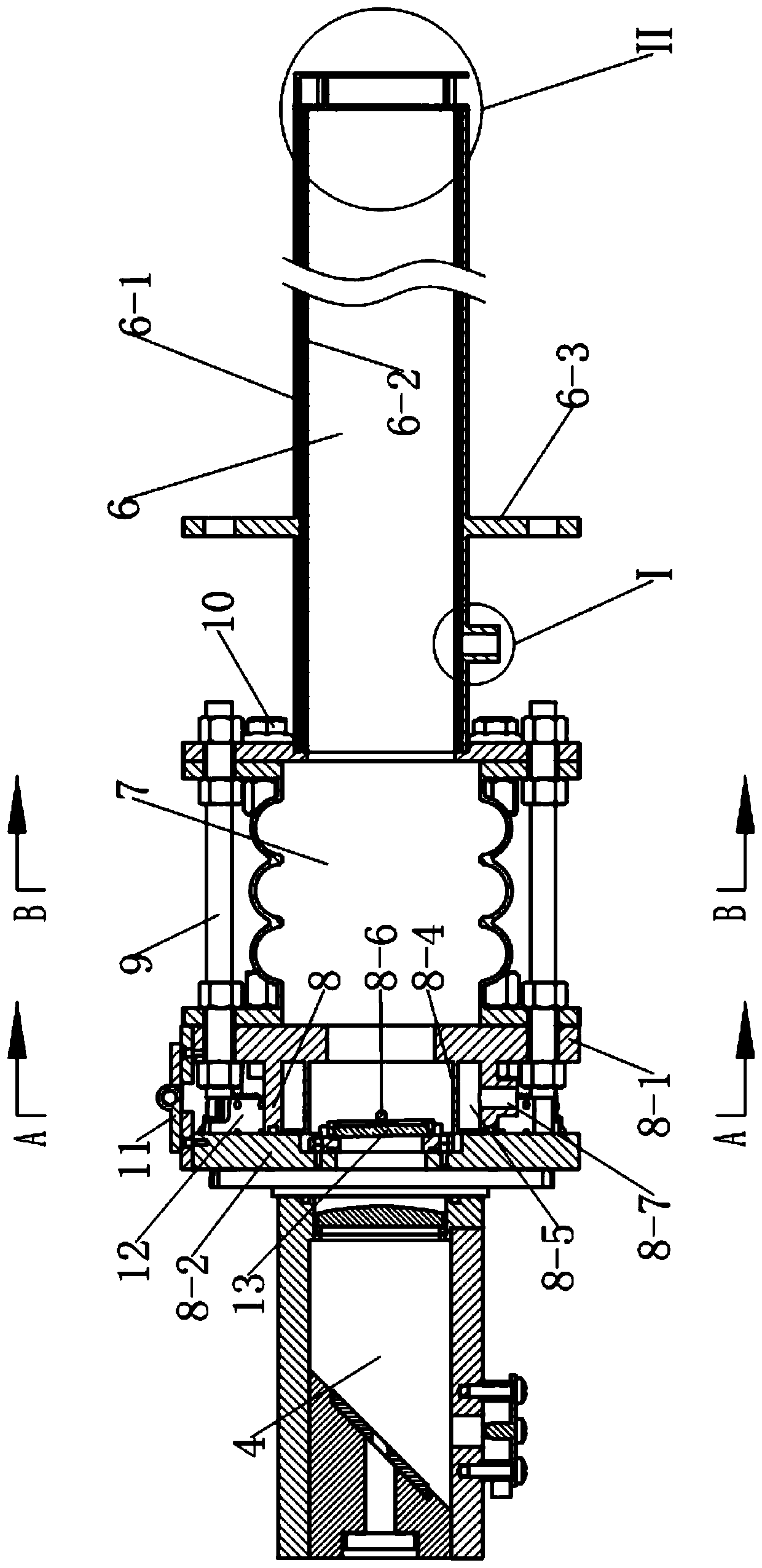
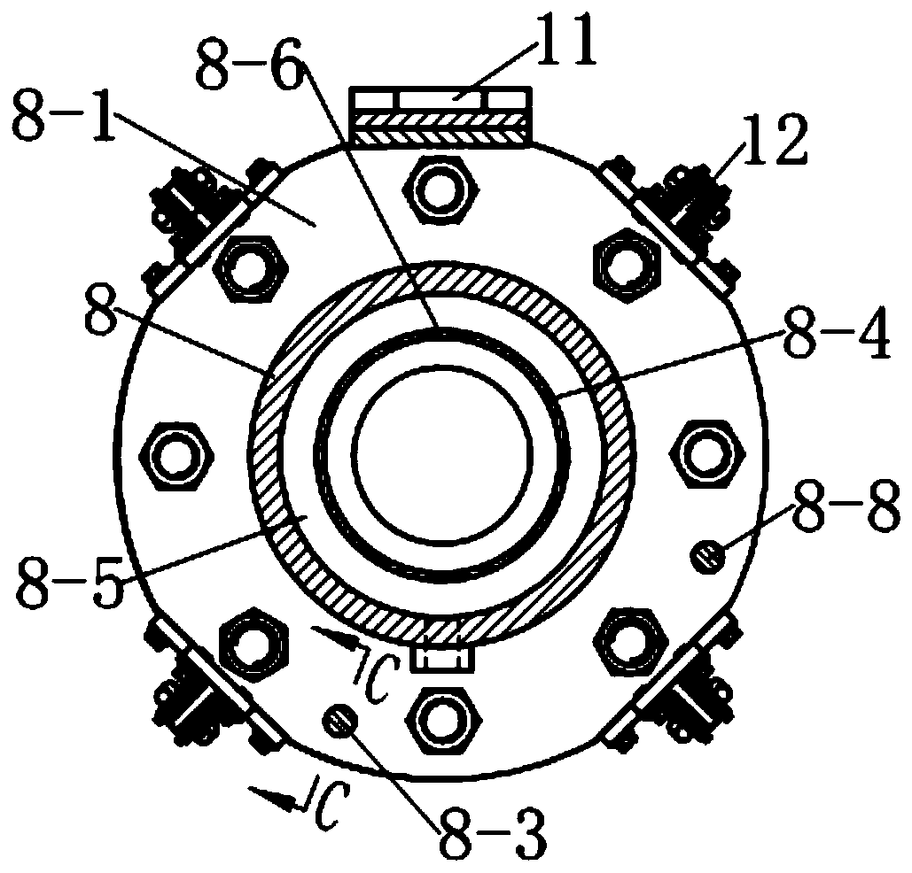
[0027] see Figure 13, The optical transceiver system of the present invention consists of a through-beam optical transceiver device, a shielding gas control device 18, gas pipelines and valves. Wherein, the described through-beam optical transceiver device is composed of an integrated laser transceiver device 15 and a laser reflection device 16; device composition. The first-stage shielding gas regulating device and the second-stage shielding gas regulating device are respectively composed of an electronic flow valve connected to an electronic flowmeter; the flow control unit is a conventional gas flow control unit, which consists of a single-chip microcomputer and a drive electronics The flow valve is composed of the driving circuit of the electronic flow meter.

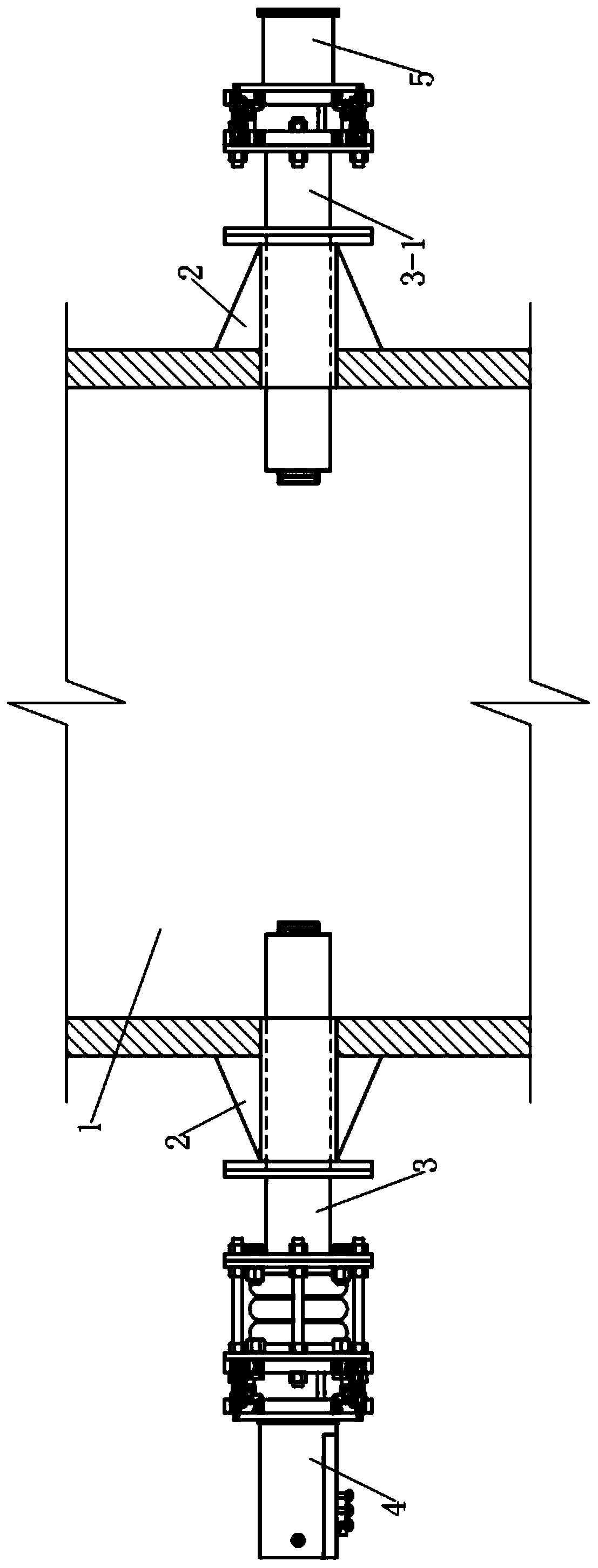
[0028] see figure 1 , the optical transceiver system of the in-situ reflective laser monitoring gas in the flue in this example includes a reflective optical transceiver, and the optical transceiver includes an...


PUM


Abstract

The invention discloses an optical transmitting-receiving system for in situ reflective laser monitoring flue gas, which comprises an optical transmitting-receiving device, wherein the optical transmitting-receiving device comprises an integral laser transmitting-receiving device and a laser reflecting device that are oppositely arranged; the integral laser transmitting-receiving device comprises a first optical path protecting cylinder and a laser transmitting-receiving module arranged at the proximal end of the first optical path protecting cylinder, and the laser reflecting device comprises a second optical path protecting cylinder and a corner reflector arranged at the proximal end of the optical path protecting cylinder; and each of the first optical path protecting cylinder and the second optical path protecting cylinder comprises, from the proximal end to the distal end, a connecting segment and an extending segment that are connected with each other. The optical transmitting-receiving system is characterized in that the integral laser transmitting-receiving device also comprises an optical path adjusting segment arranged between the connecting segment and the extending segment; and the optical path adjusting segment comprises a segment of metal corrugated pipe and four adjusting screws.

Description

technical field [0001] The present invention relates to a device or instrument for optical testing, in particular to a device for preventing components of an optical device from being stained or from being obstructed in an optical path. Background technique [0002] In response to the increasingly serious air pollution situation, countries all attach great importance to the monitoring of flue gas emissions from fixed pollution sources such as thermal power plants, metallurgical plants, chemical plants and cement plants. Flue gas pollution from industrial stationary pollution boilers. In recent years, a large number of relevant research work on the application of spectroscopy detection technology in the detection of air pollution gases has been carried out at home and abroad. Spectroscopy detection technology has many advantages such as high precision, fast response speed, and non-contact measurement. The environmental protection department realizes the regulation of flue ga...

Claims


Application Information

Patent Timeline
Patent Type & Authority Patents(China)
IPC IPC(8): G01N21/15
Inventor 尤坤张玉钧王立明何莹李宏斌李潇毅刘文清
Owner HEFEI INSTITUTES OF PHYSICAL SCIENCE - CHINESE ACAD OF SCI
Why Eureka
Try Eureka