Structure of touch panel and manufacturing method thereof

A technology of a touch panel and a manufacturing method, applied in the field of touch panel structure and its manufacture, capable of solving problems such as the influence of process stability, difficult alignment between transparent conductive electrodes 202 and peripheral circuits 280, and low yield

Inactive Publication Date: 2013-12-25
陈维钏
View PDF2 Cites 1 Cited by
  • Summary
  • Abstract
  • Description
  • Claims
  • Application Information

AI Technical Summary

Problems solved by technology

When the peripheral circuit 280 becomes thinner and the line width is lower than 50 microns, the tolerance of the glass shape will make it difficult to align the transparent conductive electrode 202 with the peripheral circuit 280, resulting in low yield
[0007] Since the lamination process still requires manual alignment and lamination, multiple alignment and lamination procedures often result in low process yield due to environmental foreign matter entering the stack or human factors, which will cause extreme stability in the process. big impact
As the peripheral lines of the touch panel move toward a narrow side-width process, the line width of the peripheral lines is reduced to less than 50 microns, which will greatly test the stability of the traditional multiple manual alignment and bonding process.

Method used


Image

  • Structure of touch panel and manufacturing method thereof
  • Structure of touch panel and manufacturing method thereof
  • Structure of touch panel and manufacturing method thereof

Examples


Embodiment Construction

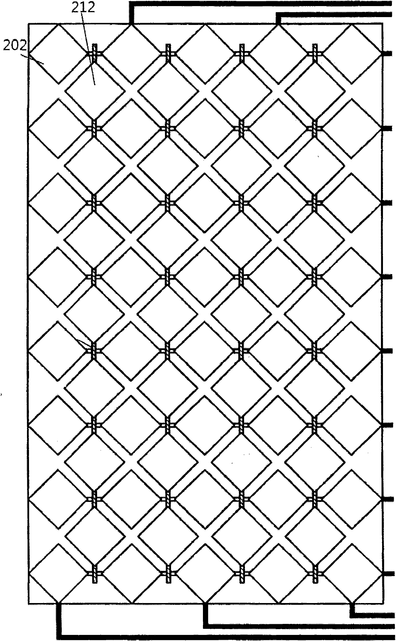
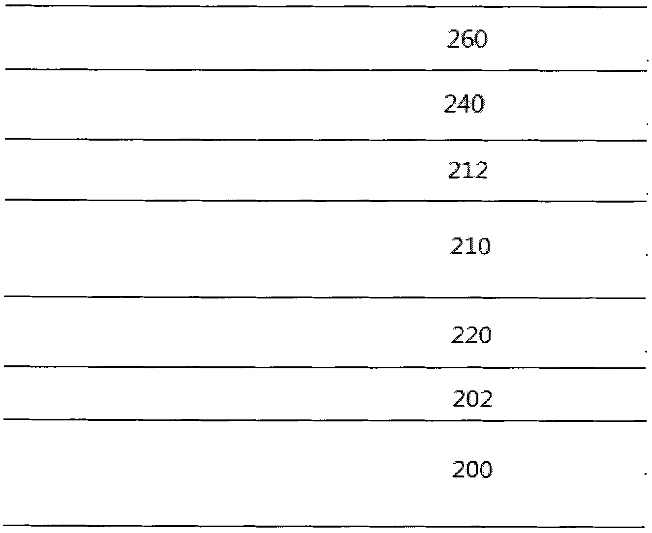
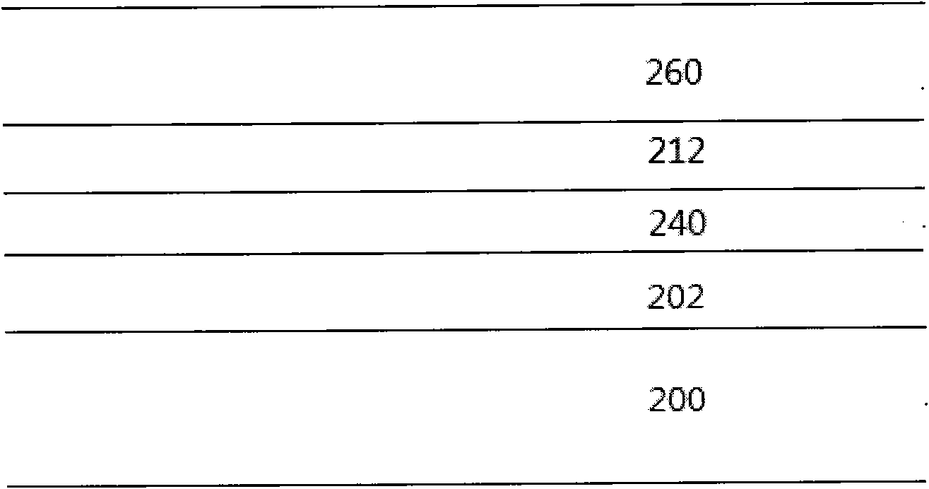
[0078] Please refer to Figure 3a to Figure 3d As shown, it is the structure of the touch panel provided by an embodiment of the present invention. in Figure 3b is along Figure 3a The sectional view shown by the section line a-a' of , Figure 3c is along Figure 3a The sectional view drawn by the section line b-b', Figure 3d is along Figure 3a The cross-sectional view shown by the section line c-c'. The touch panel of the present invention includes: a flexible transparent substrate 300 and a sensing structure 30, the flexible transparent substrate 300 has an upper surface 301 and an edge 303, the edge 303 is located on the periphery of the upper surface 301, and the sensing structure 30 is provided on the upper surface 301. The flexible transparent substrate 300 is made of a flexible material and can be rolled into a roll shape. The material of the flexible transparent substrate 300 can be, for example, one of PEN, PET, PES, flexible glass, PMMA, PC or PI, or can b...


PUM


Abstract

The touch panel of the present invention includes: a transparent base material with an upper surface and an edge, the edge is located on one side of the upper surface; a sensing structure is arranged on the upper surface of the flexible transparent base material, including: a first sensing series with The first sensing pad and the bridge line, the first sensing series is arranged on the upper surface, the first sensing pads are arranged in an array, the first bridge line is electrically connected to the first sensing pad in the first direction; the second sensing pad The pads are arranged on the upper surface in an array, and the second sensing pads are interlaced with the first sensing pads; the terminal lines are arranged on the edge; the transparent insulating protective layer is arranged on the first sensing series, the second sensing pads, On the terminal circuit and the exposed transparent base material, the transparent insulating protective layer has a connection window, and the connecting window respectively exposes a part of each second sensing pad; the second bridge line is arranged on the insulating protective layer, and the second bridge line The connection window is electrically connected to the second sensing pads adjacent to the second direction to form a second sensing series, and the terminal lines are respectively connected to the first and second sensing series.

Description

technical field [0001] The present invention is a touch panel structure and its manufacturing method, which is used to improve the complex stacking structure of the traditional capacitive touch panel, and can improve the process yield of the capacitive touch panel, and reduce the manufacturing of the projected capacitive touch panel program and reduce fitting steps. Background technique [0002] At present, capacitive touch panels have been widely used in various electronic products. In use, you only need to lightly press the touch panel with your fingers to read or input information. It can replace the buttons and keyboards on traditional electronic devices, bringing human beings Come and live conveniently. However, capacitive touch technology can be divided into two types at present, one is surface capacitive touch technology (Surface Capacitive), and the other is projected capacitive touch technology (Projected Capacitive). [0003] Capacitive touch technology detects c...

Claims


Application Information

Patent Timeline
Patent Type & Authority Patents(China)
IPC IPC(8): G06F3/044
Inventor 陈维钏
Owner 陈维钏
Why Eureka
Try Eureka