Capacitive type isolated bus with two shielded ends

An insulated bus, capacitor type technology, applied in the direction of insulators, insulated conductors, insulated cables, etc., can solve the problems of high production cost and complex process, and achieve the effects of low cost, avoiding short circuit between phases, and simple installation.

Inactive Publication Date: 2013-06-12
辽宁博际电气技术有限公司
View PDF4 Cites 0 Cited by
  • Summary
  • Abstract
  • Description
  • Claims
  • Application Information

AI Technical Summary

Problems solved by technology

[0003] In order to overcome the problems of complex process and high production cost in the shielding connection of high-voltage capacitive insulating bus bars at the present stage, the present invention proposes a double-ended shielding capacitive insulating bus bar, which mainly includes a conductive body, and the two ends of the conductive body are firmly connected Rigid insulation cylinder, one end of the rigid insulation cylinder is firmly connected with the guide body, and the other end is firmly connected with the fixed flange, there is a capacitive insulator outside the rigid insulation cylinder and the guide body, and there are socket slots at both ends of the guide body. The double-ended shielded capacitive insulated busbar does not require a separate insulated shielded intermediate connector, the structure is simple, the production cost is low, the whole process is insulated and shielded, the installation is convenient, and it can be tested in the factory. Free adjustment of thermal expansion and contraction

Method used


Image

  • Capacitive type isolated bus with two shielded ends
  • Capacitive type isolated bus with two shielded ends

Examples


Embodiment Construction

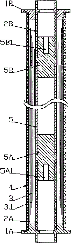
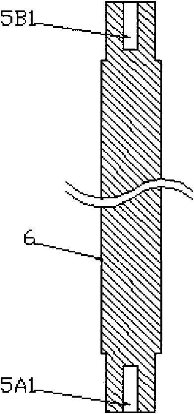
[0013] figure 1 is a structural schematic diagram of the first embodiment of the present invention, figure 1 As shown in the figure, in this embodiment, the double-ended shielded capacitive insulated bus bar mainly includes a guide body 5, rigid insulating cylinders 2A and 2B, fixed flanges 1A and 1B, and a capacitive insulator 3. It is characterized in that the guide body 5 is arranged on The center position and the two ends of the guide body are provided with plug-in terminals 5A and 5B with slots 5A1 and 5B1. The two ends of the guide body 5 are respectively connected and fixed to the rigid insulating cylinders 2A and 2B, and the other ends of the rigid insulating cylinders 2A and 2B are fixed. One end is respectively fixed on the fixed flanges 1A and 1B, and the socket ends 5A and 5B are provided with socket slots 5A1 and 5B1, and the rigid insulating cylinders 2A and 2B and the outside of the guide body 5 are provided with organic insulating tapes. The capacitive insulat...


PUM


Abstract

The invention discloses a capacitive type isolated bus with two shielded ends, aiming at solving the problems of complicate process and high manufacturing cost of the high-voltage capacitive type isolated bus in the prior art. The capacitive type isolated bus with two shielded ends, provided by the invention, mainly comprises a current guiding body, rigid isolated barrels, fixed flanges and capacitive type isolators, and is characterized in that the current guiding body is arranged at a central position and two ends of the current guiding body are respectively provided with a plugging terminal with a plugging slot; the plugging terminals at two ends of the current guiding body are respectively and fixedly connected with one rigid isolated barrel; the other terminal of each rigid isolated barrel is respectively fixed on one fixed flange; the capacitive type isolators are wrapped outside the rigid isolated barrels and the current guiding body by using organic isolated tapes; and an innermost screen of a capacitive screen of each capacitive type isolator is equipotential to the current guiding body and an outermost screen of the capacitive screen of each capacitive type isolator is reliably grounded through the corresponding fixed flange. By adopting the capacitive type isolated bus with two shielded ends, provided by the invention, an isolated shielding type intermediate connector is not needed, the capacitive type isolated bus has the advantages of simple structure, low manufacturing cost and mounting convenience, is subjected to isolated shielding in a whole course, and can be detected at a factory; and the current guiding body is connected in a plugging manner so that the bus is regulated freely in a manner of expanding under heating and contracting under cooling.

Description

technical field [0001] The invention relates to an insulated busbar of a power system, in particular to a double-end shielded capacitive insulated busbar with various voltage levels above 6kV in the power system. Background technique [0002] At present, there are 6kV ~ 40.5kV capacitive insulated busbars on the market. In order to realize the shielded connection of two busbars, two schemes are adopted: one is to make capacitive insulation on site, and the other is to add a shielding cylinder. The two solutions cannot be used in higher voltage capacitive insulated busbars due to process, cost and other reasons. Nowadays, there are still problems in the shielding connection of high voltage capacitive insulated busbars with complex process and high production cost. Contents of the invention [0003] In order to overcome the problems of complex process and high production cost in the shielding connection of high-voltage capacitive insulating bus bars at the present stage, the...

Claims


Application Information

Patent Timeline
Patent Type & Authority Patents(China)
IPC IPC(8): H01B7/00H01B7/17H01B7/40H01B17/56H01B17/62H01B5/02H02G5/00
Inventor 王日新
Owner 辽宁博际电气技术有限公司
Why Eureka
Try Eureka