A cable mold

A cable and mold technology, applied in the field of cable molds, can solve the problems of high manufacturing cost, long process consumption time, complicated manufacturing process, etc., and achieve the effect of fast production speed, less material consumption and reduced process

Active Publication Date: 2011-12-14
STATE GRID CORP OF CHINA +1
View PDF5 Cites 7 Cited by
  • Summary
  • Abstract
  • Description
  • Claims
  • Application Information

AI Technical Summary

Problems solved by technology

However, with the continuous development of technology, under the same ampacity, withstand voltage level, etc., the outer diameter of the cable is required to be smaller and smaller, and the raw materials consumed must be continuously reduced. This will not only adapt to carbon, sustainable The needs of development, and it brings new tasks to the mold design and production of cable processing; the cables in the prior art are made of circular insulated core wires and then multiple insulated core wires are twisted to form a cable core. Then it is extruded on the sheath extruder. This method makes the cable production process complicated, the number of processes increases, and the process takes a long time, resulting in untimely delivery and high manufacturing costs.

Method used


Image

  • A cable mold
  • A cable mold
  • A cable mold

Examples


Embodiment 1

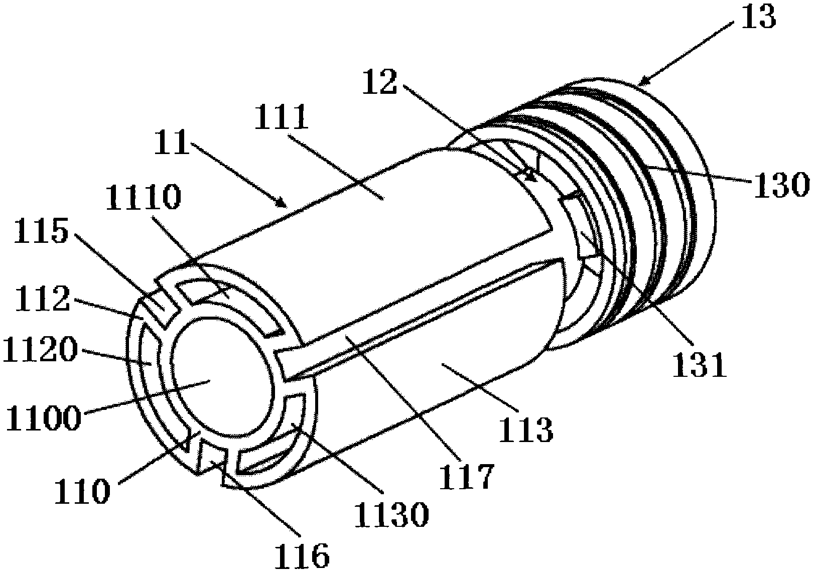
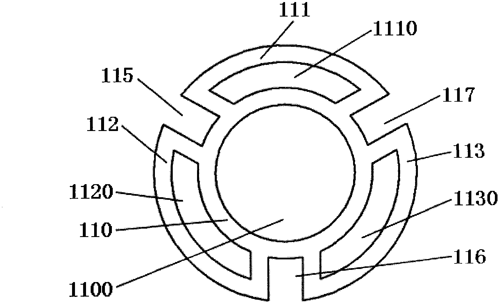
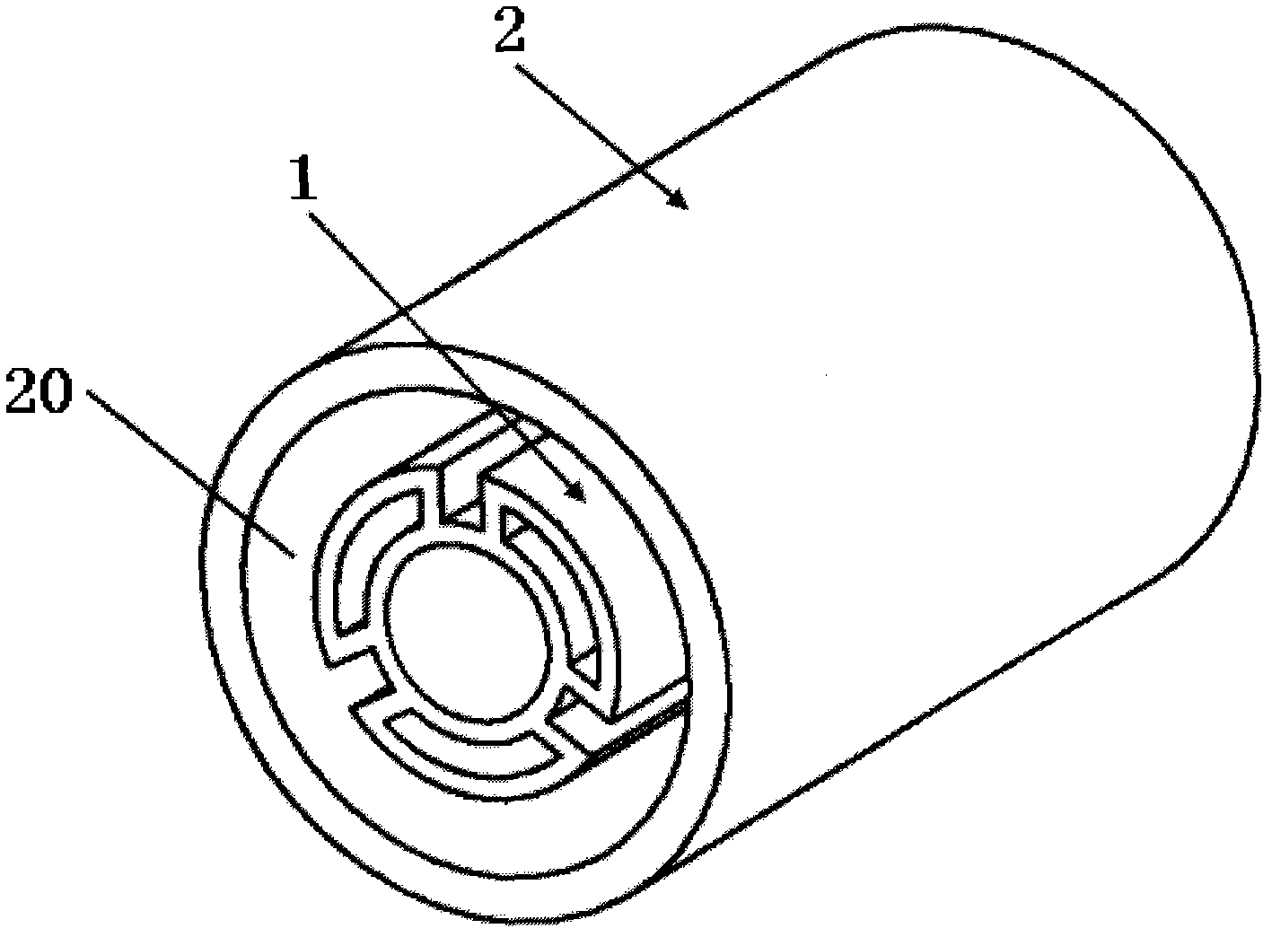
[0022] please see Figure 1 to Figure 4 , a cable mold, including a mold core 1, a mold cover 2, characterized in that the mold core is composed of a molding part 11, a transition part 12, and a connecting part 13, the molding part is located at the front end of the mold core, and the transition part is located at the middle end of the mold core , the connection part is located at the rear end of the mold core; the molding part is composed of three conductor guides (111, 112, 113), three spacer strips forming channels (115, 116, 117), and a filler guide 110, and The number of channels formed by the conductor guiding device and the spacer is equal. The conductor guiding device 111 contains a conductor hole 1110 inside, the conductor guiding device 112 contains a conductor hole 1120 inside, and the conductor guiding device 113 contains a conductor hole 1130 inside. The interior of the device contains a filling body hole 1100, the filling body guiding device is located in the cen...

Embodiment 2

[0025] please see Figure 5 and Figure 7 , and refer to Figure 1-4 A cable mold, comprising a mold core 1 and a mold cover 2, characterized in that the mold core is composed of a molding part 11, a transition part 12, and a connecting part 13, the molding part is located at the front end of the mold core, and the transition part is located at the middle end of the mold core , the connecting part is located at the rear end of the mold core; the molding part is composed of two conductor guiding devices (111, 112), two spacer strips forming channels (115, 116), and a filler guiding device 110, and the conductor guiding device and The number of channels formed by the spacers is equal, the conductor guiding device 111 contains a conductor hole 1110 inside, the conductor guiding device 112 contains a conductor hole 1120 inside, the filling body guiding device contains a filling body hole 1100 inside, and the filling body guiding device is located at the molding The filler body h...

Embodiment 3

[0028] please see Figure 6 , and refer to Figure 1-4A cable mold, comprising a mold core 1 and a mold cover 2, characterized in that the mold core is composed of a molding part 11, a transition part 12, and a connecting part 13, the molding part is located at the front end of the mold core, and the transition part is located at the middle end of the mold core , The connection part is located at the rear end of the mold core; the molding part consists of four conductor guides (111, 112, 113, 114), four spacer strips forming channels (115, 116, 117, 118), and a filler guide 110, and the number of channels formed by the conductor guiding device and the spacer is equal, the conductor guiding device 111 contains a conductor hole 1110 inside, the conductor guiding device 112 contains a conductor hole 1120 inside, and the conductor guiding device 113 contains a conductor hole 1130 inside , the conductor guiding device 114 contains a conductor hole 1140 inside, the filling body gui...


PUM


Abstract

The invention belongs to the technical field of electric wires and cables and particularly relates to a cable mold. The cable mold comprises a mold core and a mold cover and is characterized in that: the mold core consists of a forming part, a transition part and a connection part; the forming part is positioned at the front end of the mold core; the transition part is positioned at the middle end of the mold core; the connection part is positioned at the rear end of the mold core; the forming part consists of conductor guide devices, isolating bar forming channels and filling body guide devices; the quantity of the conductor guide devices is equal to that of the isolating bar forming channels; and the mold core has an integrated structure. The invention has the advantages that: the cablemold is convenient to mount and easy to manufacture, processes of producing the cables can be reduced, the cables have higher production speeds, the produced cables have smaller diameters, and the cable mold has lower material consumption and lower cost.

Description

technical field [0001] The invention belongs to the technical field of electric wires and cables, and in particular relates to a cable mold. Background technique [0002] In the prior art, cables have been widely used, and there are various molds for producing cables, but the technology has matured. However, with the continuous development of technology, under the same ampacity, withstand voltage level, etc., the outer diameter of the cable is required to be smaller and smaller, and the raw materials consumed must be continuously reduced. This will not only adapt to carbon, sustainable The needs of development, and it brings new tasks to the mold design and production of cable processing; the cables in the prior art are made of circular insulated core wires and then multiple insulated core wires are twisted to form a cable core. Then it is extruded on the sheath extruder. This method makes the cable manufacturing process complicated, the number of processes increases, and t...

Claims


Application Information

Patent Timeline
IPC IPC(8): H01B13/14B29C47/12B29C48/30
Inventor 方亚琴蒋菊生
Owner STATE GRID CORP OF CHINA
Why Eureka
Try Eureka