micro sounder

A sound generator, miniature technology, applied in the direction of sensors, electrical components, etc., can solve problems such as increased distortion, limited voice coil winding height, and reduced product sensitivity.

Inactive Publication Date: 2011-12-14
AAC ACOUSTIC TECH (SHENZHEN) CO LTD +1
View PDF1 Cites 2 Cited by
  • Summary
  • Abstract
  • Description
  • Claims
  • Application Information

AI Technical Summary

Problems solved by technology

However, such a voice coil structure limits the winding height of the voice coil. In the design of high-power products, the increase of the vibration space will cause the position of the voice coil in the magnetic gap to be higher, and the asymmetric distribution will lead to the failure of the product. Sensitivity decreases, distortion increases

Method used


Image

  • micro sounder
  • micro sounder
  • micro sounder

Examples


Embodiment Construction

[0016] The present invention will be further described below in conjunction with the accompanying drawings and embodiments.

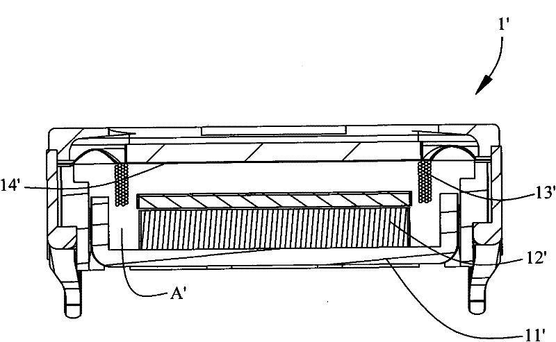
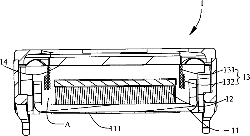
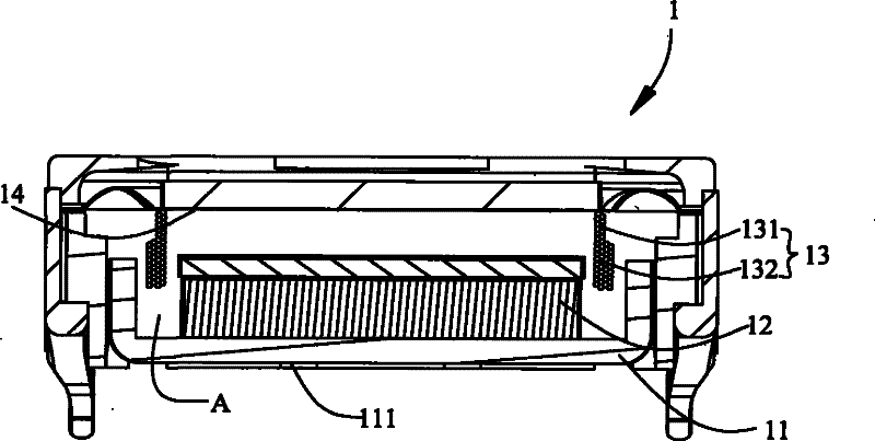
[0017] A micro sounder 1 provided by the present invention comprises a magnetic bowl 11, a magnetic steel 12 accommodated in the magnetic bowl 11, a coil 13 partially accommodated in the magnetic gap A formed by the magnetic bowl 11 and the magnetic steel 12, and a coil 13 connected to the The diaphragm 14 at one end of the coil 13 . Wherein the magnetic bowl 11 and the magnetic steel 12 constitute a magnetic circuit system. However, the magnetic circuit system is not limited thereto, and may be a multi-magnetic steel structure, or a T-iron. The present invention is only explained by taking the magnetic circuit system formed by the magnetic bowl and the magnetic steel as an example.

[0018] Wherein, the magnetic bowl 11 includes a bottom surface 111 for placing the magnetic steel 12, the coil 13 includes a first part 131 close to the diaphragm and a ...


PUM


Abstract

The invention relates to a miniature sounder, which includes a magnetic circuit system, the magnetic circuit system is provided with a magnetic gap, the miniature sounder also includes a coil partially accommodated in the magnetic gap and a diaphragm connected to one end of the coil, the coil includes a The first part of the metal wire winding of the diaphragm and the second part electrically connected to the first part and away from the metal wire winding of the diaphragm, the cross-sectional area of ​​the second part in the direction perpendicular to the coil vibration is larger than that of the first part in the direction perpendicular to The cross-sectional area of ​​the coil in the direction of vibration. Sensitivity can be improved.

Description

technical field [0001] The invention relates to a miniature sound generator. Background technique [0002] Miniature sound generating devices are widely used in portable electronic devices such as mobile phones, notebook computers, and hearing aids. With the rapid development of these portable electronic devices, people's functional requirements are getting stronger and stronger, and the miniature sound-generating devices applied to them are also developing correspondingly and rapidly. [0003] The micro-sounding device of the related structure mainly includes a bowl-shaped base, an upper cover connected to the base and provided with a sound hole, and the base and the upper cover form a receiving cavity. The accommodating cavity is provided with a permanent magnet and a pole piece housed in the base and forming a magnetic gap with the base, a diaphragm adjacent to the upper cover, a voice coil connected with the diaphragm and suspended in the magnetic gap, A circuit board ...

Claims


Application Information

Patent Timeline
Patent Type & Authority Applications(China)
IPC IPC(8): H04R9/06H04R9/04H04R31/00
Inventor 沈涛
Owner AAC ACOUSTIC TECH (SHENZHEN) CO LTD
Why Eureka
Try Eureka