Constant current power supply
A technology of constant current power supply and DC power supply, which is applied in the direction of electric light source, light source, electric lamp circuit layout, etc., can solve the problems of unfavorable popularization and high cost, and achieve the effect of no harmonic radiation, low cost and simple circuit
Inactive Publication Date: 2011-12-14
TIANJIN KINGSTAR TECH
View PDF3 Cites 0 Cited by
- Summary
- Abstract
- Description
- Claims
- Application Information
AI Technical Summary
Problems solved by technology
At present, the existing LED driving power uses many kinds of components, which is high in cost and is not conducive to popularization and use.
Method used
View moreImage
Smart ImageViewing Examples
Examples
specific example
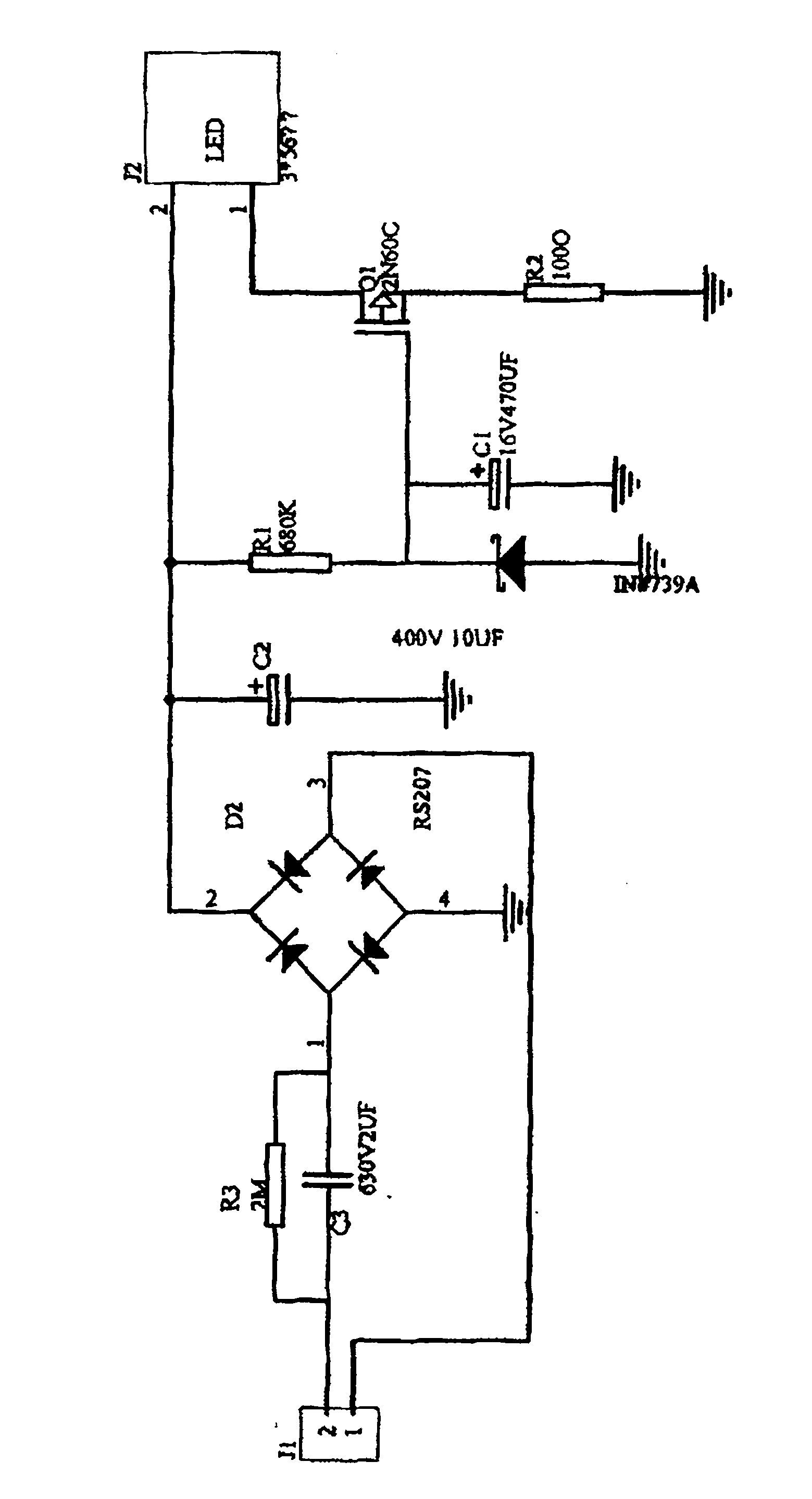
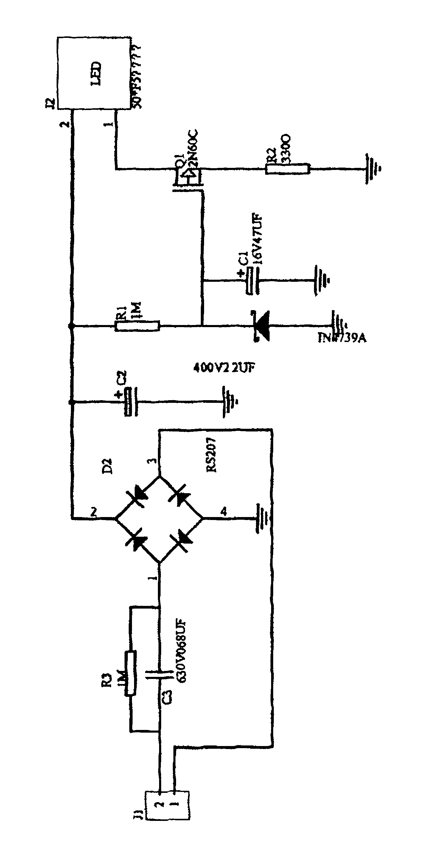
[0016] Specific examples: figure 2 , image 3 It is a 10W instance of low cost LED constant current power supply and a 3.5W instance of low cost LED constant current power supply.
Login to View More PUM
 Abstract
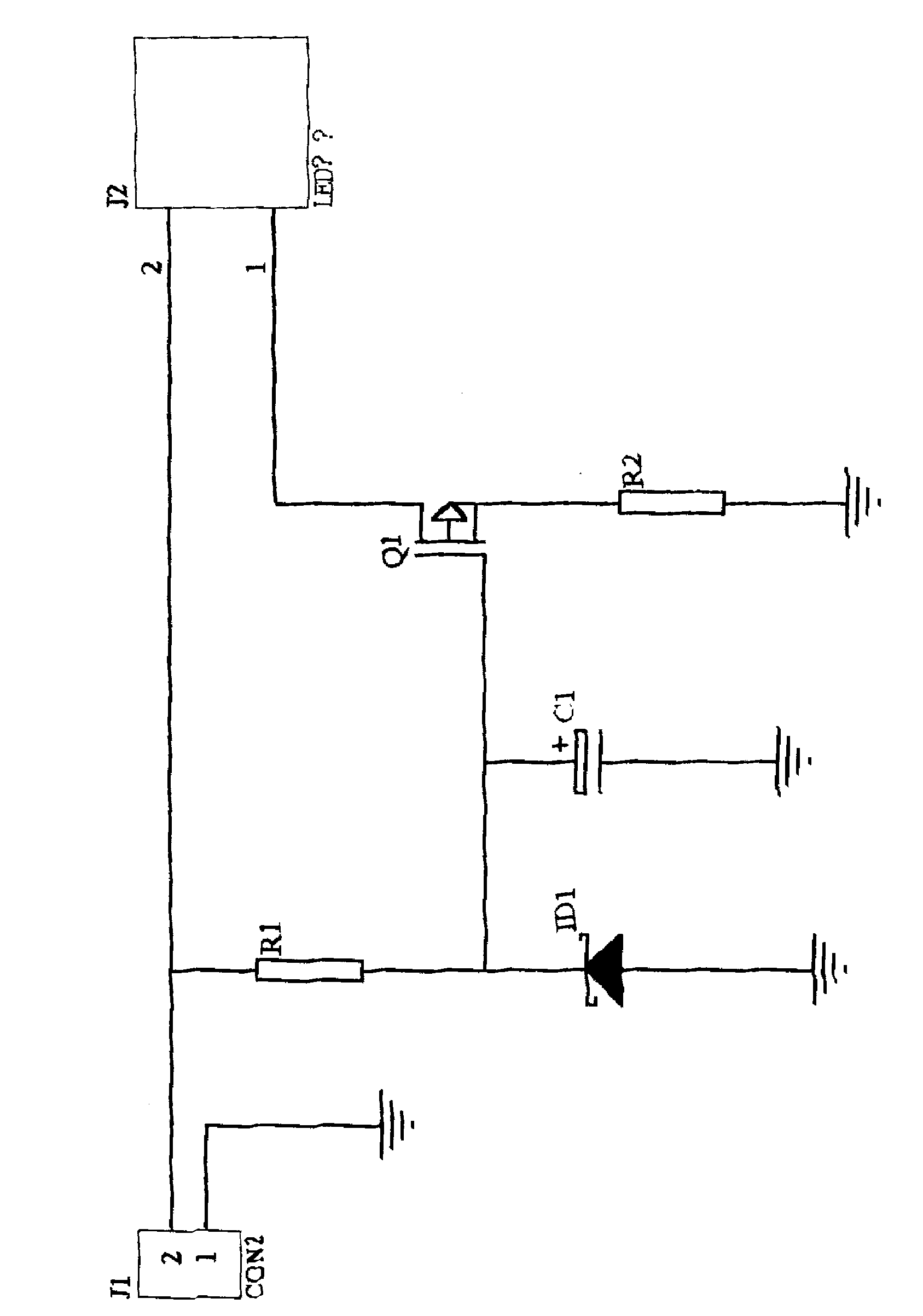
A constant current power supply, the positive terminal of the DC power supply is grounded, the negative terminal of the power supply is connected to one end of the LED tube and one end of the resistor R1, and the other end of the resistor R1 is connected to one end of the voltage regulator tube ID1, one end of the capacitor C1, the control electrode of the chip 2N60C, and the emitter of the chip 2N60C Connect one end of the resistor R2, the collector of the chip 2N60C is connected to the other end of the LED tube, the other end of the regulator tube ID1, the other end of the capacitor C1 and the other end of the resistor R2 are grounded. The low-cost LED constant-current source is a low-cost constant-current source using only five original devices, and has the advantages of simple circuit, reliability, no harmonic radiation, and low cost. It is a low-cost constant current source that provides stable and reliable current. Using a low-cost LED constant current source can give full play to the advantages of high efficiency and long life of LED components. It can be applied to small and medium power LED lighting appliances.
Description
technical field [0001] The invention belongs to LED power supply, in particular to a constant current power supply. Background technique [0002] One of the keys to white LED lighting technology is the LED drive power supply, whose main function is to provide stable and reliable current. At present, the existing LED driving power adopts many kinds of components and parts, and the cost is high, which is not conducive to popularization and use. Contents of the invention [0003] The technical problem to be solved by the present invention is to provide a constant current power supply. [0004] Technical scheme of the present invention is: [0005] A constant current power supply, characterized in that: it is an LED constant current power supply composed of five components: the positive end of the DC power supply is grounded, the negative end of the power supply is connected to one end of the LED tube and one end of the resistor R1, and the other end of the resistor R1 is co...
Claims
Login to View More Application Information
Patent Timeline
 Patent Type & Authority Applications(China)
IPC IPC(8): H05B37/02
Inventor 李津尧
Owner TIANJIN KINGSTAR TECH
Features
- R&D
- Intellectual Property
- Life Sciences
- Materials
- Tech Scout
- Unparalleled Data Quality
- Higher Quality Content
- 60% Fewer Hallucinations
Learn More Browse by: Latest US Patents, China's latest patents, Technical Efficacy Thesaurus, Application Domain, Technology Topic, Popular Technical Reports.
© 2025 PatSnap. All rights reserved.Legal|Privacy policy|Modern Slavery Act Transparency Statement|Sitemap|About US| Contact US: help@patsnap.com


