Synchronous core-pulling mechanism on the inner and outer sides of the injection mold for automobile wheel covers

A technology of injection mold and core-pulling mechanism, which is applied in the field of synchronous core-pulling mechanism on both sides of the inside and outside, can solve the problems of high mold cost, high production cost, complex mechanism, etc., and meet the requirements of shortening the working schedule and shortening the work opening The effect of simplifying the drive mechanism

Active Publication Date: 2011-12-21
宁波宇升模塑有限公司
View PDF4 Cites 4 Cited by
  • Summary
  • Abstract
  • Description
  • Claims
  • Application Information

AI Technical Summary

Problems solved by technology

[0002] Injection molding of automotive wheel cover products requires demoulding and core pulling on both sides of the product. The existing technology uses an asynchronous method of first outside and then inside to pull the core on both sides of the product, that is, use the mold to open the mold and move the mold back. , the movable and fixed molds are separated, and the core-pulling slider embedded in the outer side of the product is driven by the inclined guide column to complete the external lateral core-pulling. The internal lateral core pulling is completed, and finally the ejector rod is pushed by the top plate to push the product out of

Method used


Image

  • Synchronous core-pulling mechanism on the inner and outer sides of the injection mold for automobile wheel covers
  • Synchronous core-pulling mechanism on the inner and outer sides of the injection mold for automobile wheel covers
  • Synchronous core-pulling mechanism on the inner and outer sides of the injection mold for automobile wheel covers

Examples


Embodiment Construction

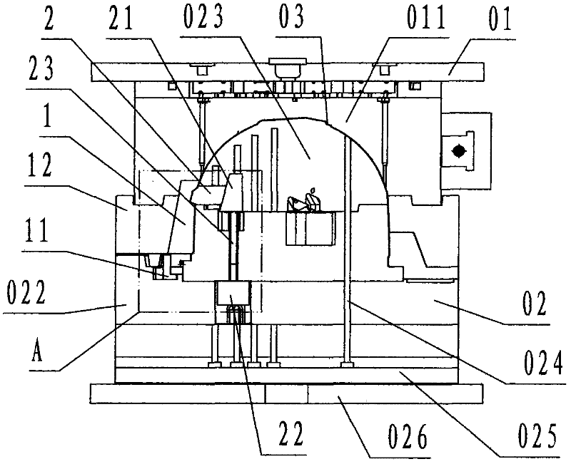
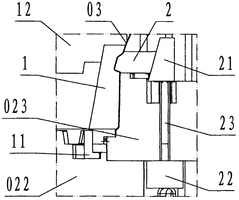
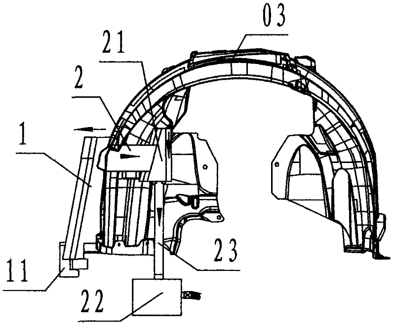
[0024] refer to Figure 1 ~ Figure 3 , a synchronous core-pulling mechanism on both sides of the inner and outer sides of an automobile wheel cover injection mold according to the present invention, comprising an outer core-pulling slider 1, an oblique guide block 12, an inner core-pulling slider 2, an oblique wedge slider 21, an oil cylinder 22, a connecting Rod 23, wherein: the outer core-pulling slider 1 is a steel block with a rectangular top view projection and a trapezoidal trapezoidal shape with a small top and a large bottom bottom in a side view projection. One side of the outer core-pulling slider 1 is a slope, so The T-shaped groove along the inclined plane direction on the slope is called the chute side, and the side opposite to the chute side is called the profile side. The core-pulling profile, the bottom surface of the outer core-pulling slider 1 is provided with a hook 11 composed of an L-shaped right-angled hook-shaped block, and the opening of the hook groove...


PUM


Abstract

The invention discloses an inside and outside synchronous core pulling mechanism of a vehicle wheel cover injection mould, which comprises an outside core pulling slide block (1), an oblique guide block (12), an inside core pulling slide block (2), an oblique wedge slide block (21), an oil cylinder (22) and a connecting rod (23). The outside core pulling slide block is glidingly arranged at the core pulling forming place on the outer side of a dynamic model core; the oblique guide block is fixedly arranged at a fixed model cavity; an opening mould is used for driving the outside core pulling slide block to perform core pulling movement outwards; a mechanism consisting of the oil cylinder, the connecting rod and the oblique wedge slide block is arranged in the dynamic model core and a dynamic template at the core pulling forming place of the inside core pulling slide block; and the oil cylinder is used for driving the inside core pulling slide block to perform core pulling movement inwards. Due to the adoption of the technical scheme that core pulling is performed on the inner side and the outer side of a product at the same time, the problems and disadvantages of complex mechanism, big volume and high cost of the prior art are solved and overcome, and the aims of simplifying the mechanism, reducing the volume and reducing the cost of the vehicle wheel cover injection mould arefulfilled.

Description

technical field [0001] The invention relates to a core-pulling and demoulding mechanism of an injection mold, in particular to an automobile wheel cover which is applied to an injection mold of an automobile wheel cover and is used for simultaneously performing core-pulling and demoulding on the inner and outer sides of an injection-molded automobile wheel cover product The inner and outer sides of the injection mold are synchronized with the core-pulling mechanism. Background technique [0002] Injection molding of automotive wheel cover products requires demoulding and core pulling on both sides of the product. The existing technology uses an asynchronous method of first outside and then inside to pull the core on both sides of the product, that is, use the mold to open the mold and move the mold back. , the movable and fixed molds are separated, and the core-pulling slider embedded in the outer side of the product is driven by the inclined guide column to complete the ext...

Claims


Application Information

Patent Timeline
IPC IPC(8): B29C45/33B29C45/40
Inventor 叶元建顾宏科
Owner 宁波宇升模塑有限公司
Why Eureka
Try Eureka