Precise positioning to form local laser pattern process

A precise positioning and patterning technology, applied in the printing process, printing, printing of special varieties of printed matter, etc., can solve the problems of dazzling, unclear layers, and abruptness.

Inactive Publication Date: 2011-12-21
SHANTOU KINGSPACK TECH
View PDF4 Cites 3 Cited by
  • Summary
  • Abstract
  • Description
  • Claims
  • Application Information

AI Technical Summary

Problems solved by technology

The first type of structure is that there is no pattern on the packaging film except for the local laser pattern, and the surrounding edge is purely transparent plastic film. Therefore, the laser pattern appears lonely, abrupt, and poor in integrity, and the overall graphic and color information of the packaging film is too little
The second structural form is to coat the entire packaging film with an aluminum layer after the local laser pattern is formed. Since the thickness of the aluminum layer is extremely thin, the concave-convex texture of the laser pattern is still a concave-convex texture after the aluminum layer is coated. It has the same laser pattern effect; but the disadvantage of the second structure is: the whole packaging film (including the laser part and the non-laser part) is shiny silver, the contrast is not big, the laser part is not prominent, and the whole is dazzling. The focus is not obvious, the level is not clear

Method used


Image

  • Precise positioning to form local laser pattern process
  • Precise positioning to form local laser pattern process
  • Precise positioning to form local laser pattern process

Examples


Embodiment 1

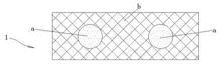
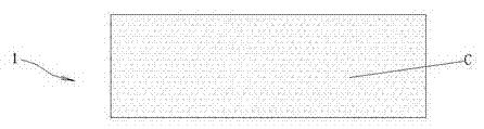
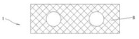
[0031]The process of precisely positioning and forming a local laser pattern includes the following steps in sequence: (1), designing the ideal position and shape of the laser pattern area and the ink printing area, and making the designed ink printing area b cover the periphery of the designed laser pattern area a , there is no gap between the design laser pattern area a and the design ink printing area b, and the two are seamlessly connected, such as figure 1 (2) Print the laser pattern on the entire printing film 1 to form a semi-finished laser pattern area C. The semi-finished laser pattern area C not only covers the designed laser pattern area a, but also exceeds the designed laser pattern area from all directions around it. a, such as figure 2 (3) Precisely print light golden yellow ink on the design ink printing area b by ink printing, thereby forming a light golden yellow ink printing area B on the printing film 1, and the golden yellow ink printing area B is as follo...

Embodiment 2

[0033] The process of precisely positioning and forming a local laser pattern includes the following steps in sequence: (1), designing the ideal position and ideal shape of the laser pattern area, and simultaneously designing the ideal position and ideal shape of the ink printing area, and making the designed ink printing area b set On the periphery of the designed laser pattern area a, there is no gap between the designed laser pattern area a and the designed ink printing area b, and the two are seamlessly connected, such as Figure 6 (2), print the laser pattern on the printing film 1 to form a "semi-finished laser pattern area C", such as Figure 7 As shown, the semi-finished laser pattern area C not only covers the design laser pattern area a, but also exceeds the design laser pattern area a from all directions around, as Figure 8 shown in Figure 8 Among them, the line 11 in the outer circle represents the edge line of the semi-finished laser pattern area C, and the lin...


PUM


Abstract

The invention relates to a process for forming local laser patterns by accurately positioning, which sequentially comprises the following steps of: (1) designing ideal positions and shapes for a laser patterned area and an ink printed area, and sleeving a designed ink printed area b at the periphery of a designed laser patterned area a; (2) forming a semi-finished laser patterned area C on a printing-bearing film, and enabling the laser patterned area C to cover the designed laser patterned area a and exceed the designed laser patterned area a from each direction all around; and (3) accurately printing ink on the designed ink printed area b by using an ink-printing manner to form an ink printed area B, wherein the ink fills up concave and convex grains of laser patterns on an overlapped part of the ink printed area B and the semi-finished laser patterned area C, the laser effect of the overlapped part vanishes, the semi-finished laser patterned area is shortened to a laser patterned area A and then the printing-bearing film capable of being accurately sleeved with the laser patterned area A and the ink printed area B is obtained. The process for forming the local laser patterns byaccurately positioning can enable the ink printed area to be accurately sleeved with the laser patterned area.

Description

[0001] technical field [0002] The invention belongs to the technical field of printing laser patterns, and in particular relates to a process for forming local laser patterns with precise positioning. Background technique [0003] In the existing printing technology, the technology of printing ink printing area on the printing film with precise positioning is very mature, but it is still difficult to form a local laser pattern with precise positioning. This is due to the obvious difference in the printing process of the two: the local ink area is to print the ink layer on the part of the printing material, and very traditional processes such as gravure printing and embossing can be used, and these processes can achieve precise positioning. Precise positioning, so the ink layers at different positions can be nested very precisely, that is, one ink pattern is precisely nested around the other ink pattern, and there is no gap between the two ink patterns; while the local lase...

Claims


Application Information

Patent Timeline
Patent Type & Authority Applications(China)
IPC IPC(8): B41M3/00
Inventor 李飚诸荣建康忠凯
Owner SHANTOU KINGSPACK TECH
Why Eureka
Try Eureka