Aircraft Rear Fuselage Tail Cone Structure with Auxiliary Power Unit

A technology of auxiliary power unit and rear fuselage, applied in the field of aviation industry, can solve a lot of time and cost problems

Inactive Publication Date: 2011-12-21
AIRBUS OPERATIONS SL
View PDF6 Cites 8 Cited by
  • Summary
  • Abstract
  • Description
  • Claims
  • Application Information

AI Technical Summary

Problems solved by technology

The problem with this type of APU support is that it takes a lot of time and expense to complete the installation

Method used


Image

  • Aircraft Rear Fuselage Tail Cone Structure with Auxiliary Power Unit
  • Aircraft Rear Fuselage Tail Cone Structure with Auxiliary Power Unit
  • Aircraft Rear Fuselage Tail Cone Structure with Auxiliary Power Unit

Examples


Embodiment Construction

[0074] The following description is provided for the convenience of the reader only and is not intended to limit the invention, as set forth in the claims, in any way.

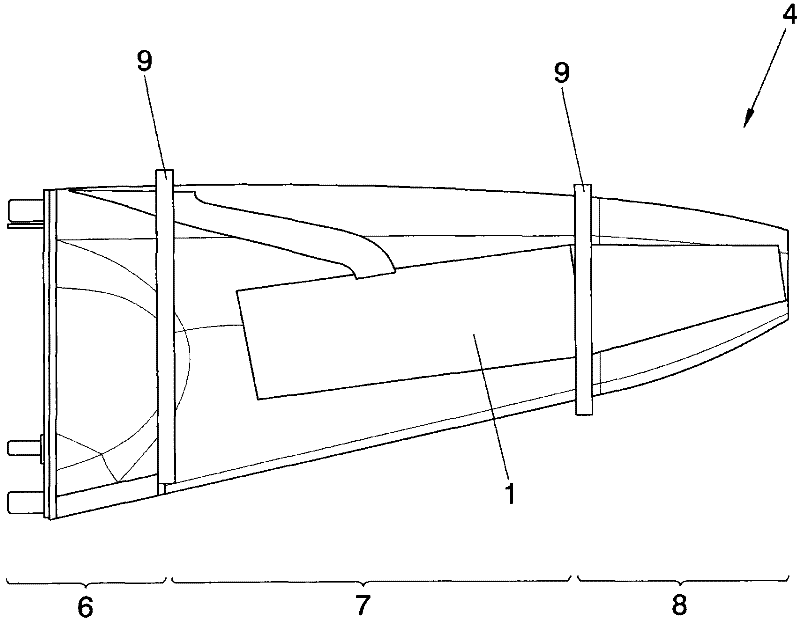
[0075] figure 1 The rear fuselage tail cone 4 of the aircraft is shown showing where the fire compartment 7 is located between the tail cone fuselage interface 6 and the exhaust tail cone end 8 separated by a fire wall 9 .

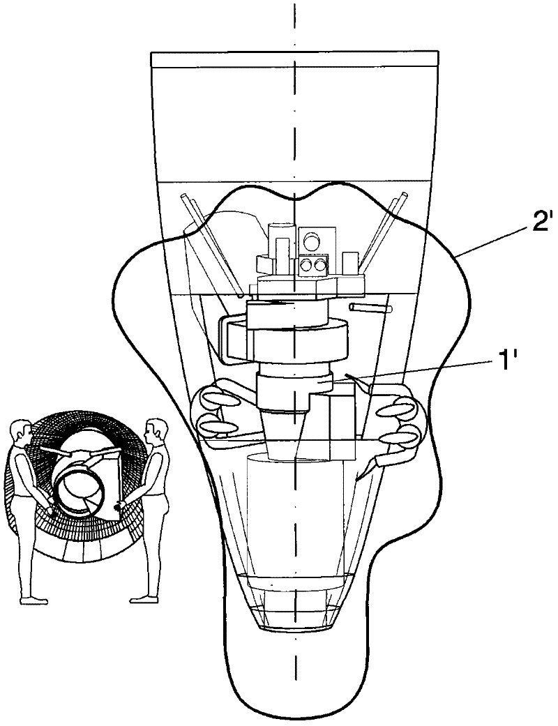
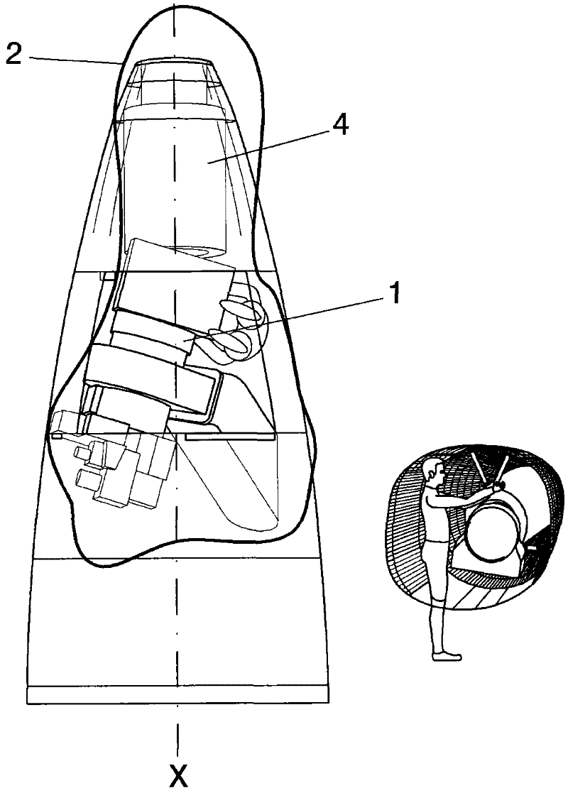
[0076] figure 2 and image 3 The traditional symmetrical layout of the APU 1' and the asymmetrical layout of the APU 1 proposed by the present invention with respect to the longitudinal axis X of the aircraft are shown respectively, from which it can be seen that the maintenance cover 2 or envelope required by the present invention to perform maintenance tasks is significantly smaller than Maintenance cover 2' of prior art.

[0077] Figure 3a An example of an asymmetrical arrangement is shown, namely lateral asymmetry, where, for example purposes only, it is shown that the inclinatio...


PUM

PropertyMeasurementUnit
angleaaaaaaaaaa

Abstract

Configuration of a rear fuselage tail cone of an aircraft with an auxiliary power unit, whereby a fire compartment of the rear fuselage tail cone defines a housing for the auxiliary power unit in which the auxiliary power unit is housed laterally and asymmetrically with respect to a longitudinal axis (X) of the rear fuselage tail cone and the auxiliary power unit is directly fasten attached to a structural skin wall of the housing. Additionally, by struts or rods attached to opposite side and upper structural skin wall of the fire compartment.

Description

[0001] purpose of invention [0002] The object of the present invention is to obtain an optimal relationship between the parasitic drag generated by an aircraft in flight and the increasing size of the auxiliary power unit (hereinafter referred to as "APU") due to the increasing power requirements of the aircraft . This means that the invention aims to solve the problem of installing a bulky APU in a small space, ie in the small space of the tail cone of the rear fuselage. Furthermore, the object of the invention can be expressed as reducing the size of the tail cone of the rear fuselage while also accommodating the increasing size of the APU. [0003] In order to achieve the above object, the present invention describes a new arrangement of APU in the fire compartment of the tail cone of the rear fuselage. [0004] Another object of the invention relates to a support device associated with the new arrangement mentioned here. [0005] A further object of the present inventio...

Claims


Application Information

Patent Timeline
Patent Type & Authority Applications(China)
IPC IPC(8): B64D27/26B64C1/16B64F1/36
CPCB64C1/068B64D41/00Y02T50/54Y10T29/49947
Inventor P·T·桑斯马蒂内斯
Owner AIRBUS OPERATIONS SL
Why Eureka
Try Eureka