Strip waste edge winding device

A winding device and strip-shaped technology, which is applied in the directions of transportation and packaging, conveying filamentous materials, thin material processing, etc., can solve the problems of uneven and tidy winding, unfavorable recycling, and affecting the appearance of the workshop, etc., to achieve Compact structure, good for recycling, easy to operate

Inactive Publication Date: 2011-12-21
蚌埠市天一包装制品有限责任公司
8 Cites 13 Cited by

AI-Extracted Technical Summary

Problems solved by technology

[0003] At present, in the production process of papermaking, bag making and textile industries, a large number of strip-shaped waste edges are often formed. These strip-shaped waste edges are basically scattered in the workshop, and they will be treated as waste after accumulation. Occupying the space of the workshop, the second is to affect the appearance of the w...

Abstract

The invention discloses a strip-shaped waste edge winding device. The winding disk is supported and fixed through the bearing seat on the frame through its central rotating shaft. One end of the rotating shaft is provided with a transmission wheel, and the frame is provided with a reciprocating shaft and a transition shaft. and the motor, one end of the reciprocating shaft is provided with a transmission wheel, two transmission wheels are arranged side by side on the transition shaft, two transmission wheels are arranged side by side on the output shaft of the motor, and one transmission wheel on the output shaft of the motor passes through the transmission bar and the transmission wheel on the reciprocating shaft. The transmission wheel is connected, and a slider is assembled on the reciprocating shaft to reciprocate and slide along the axial direction of the reciprocating shaft. The slider is connected to a reciprocating rod, and the outer end of the reciprocating rod is provided with a guide ring. A transmission wheel on the transition shaft is connected, and another transmission wheel on the transition shaft is connected with the transmission wheel on the winding reel rotating shaft through a transmission bar. The winding of the invention is uniform and tidy, which is beneficial to reuse, and at the same time greatly reduces the labor intensity, and significantly improves the winding efficiency.

Application Domain

Filament handling

Technology Topic

Wheel driveEngineering +2

Image

  • Strip waste edge winding device
  • Strip waste edge winding device
  • Strip waste edge winding device

Examples

  • Experimental program(1)

Example Embodiment

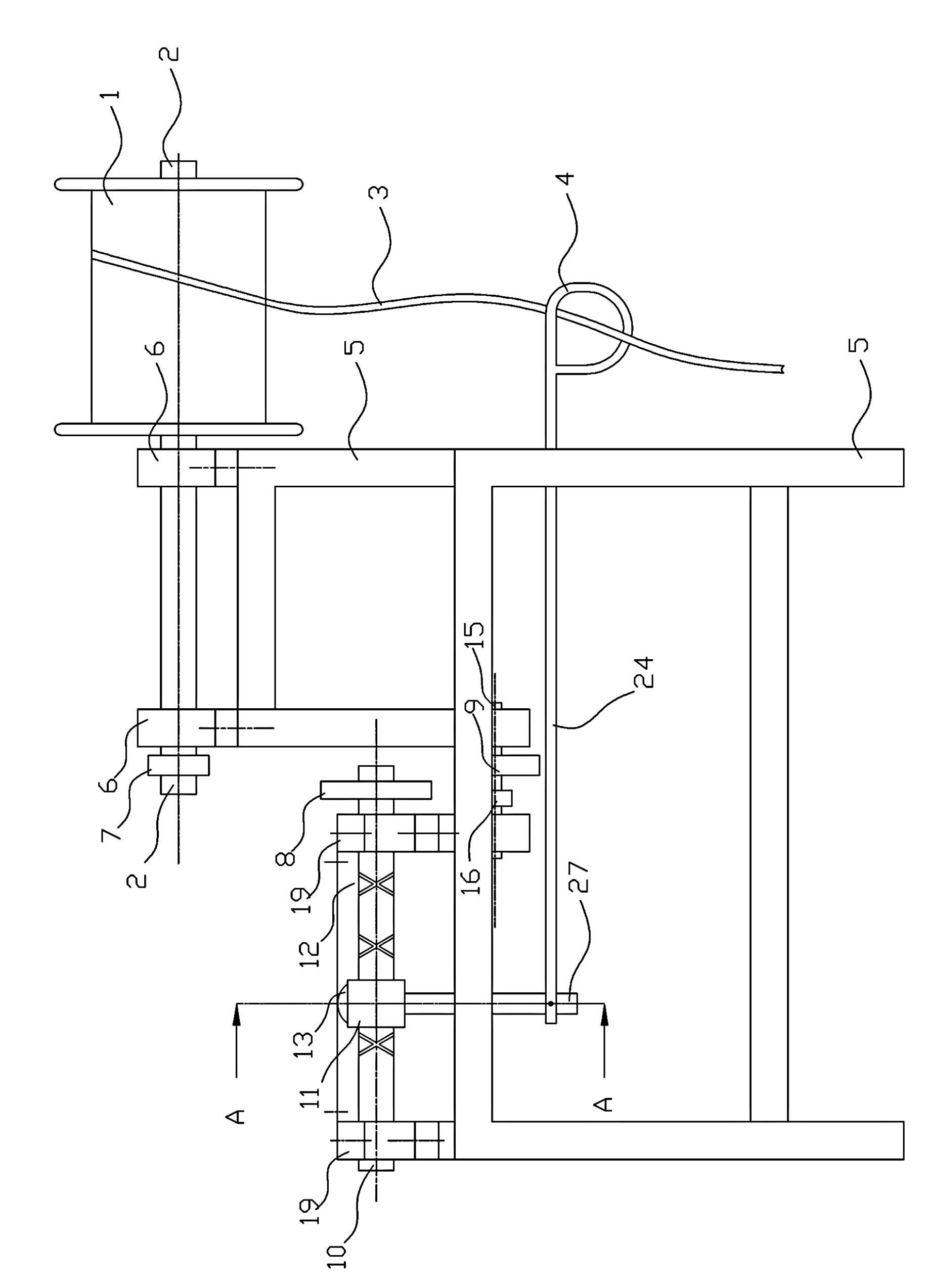
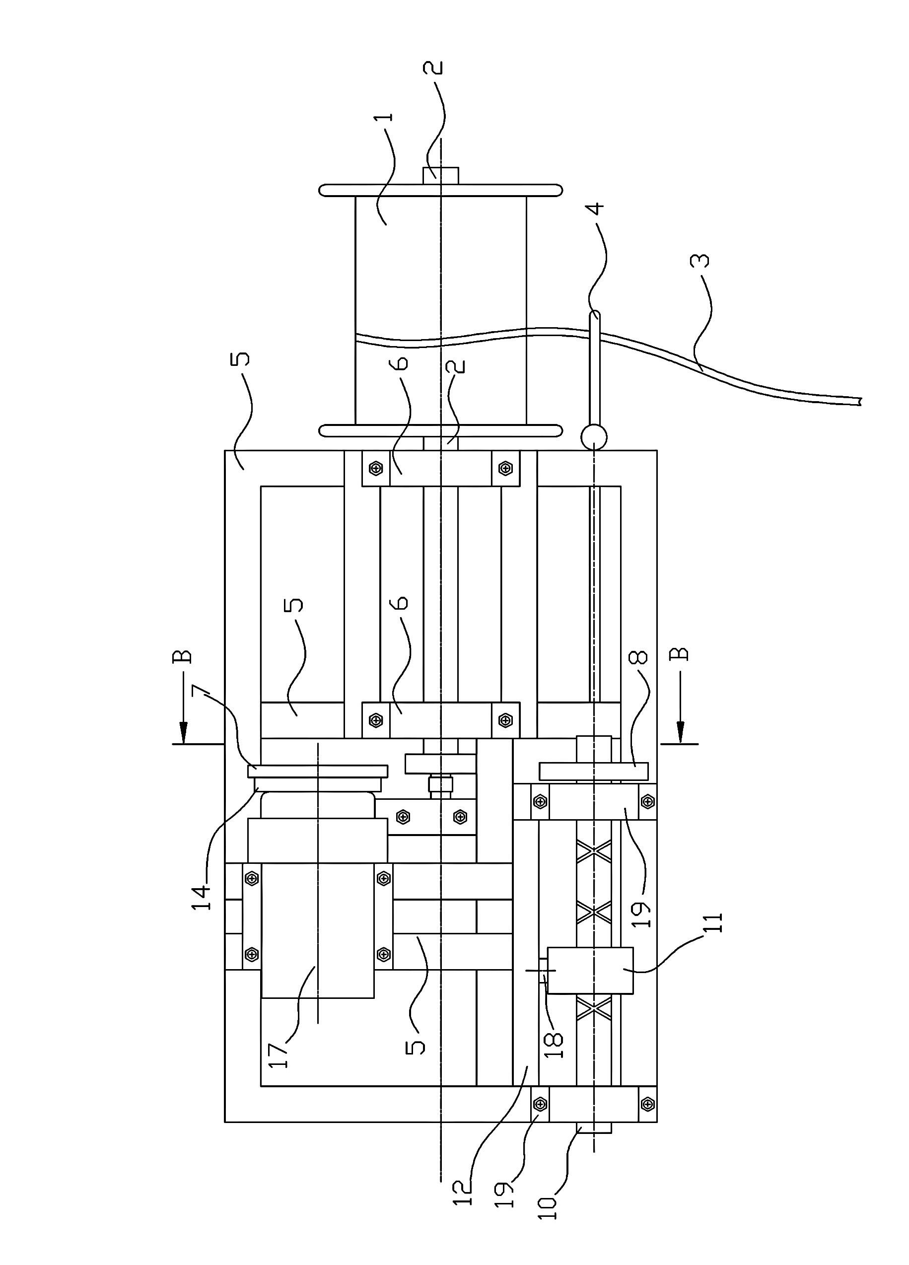
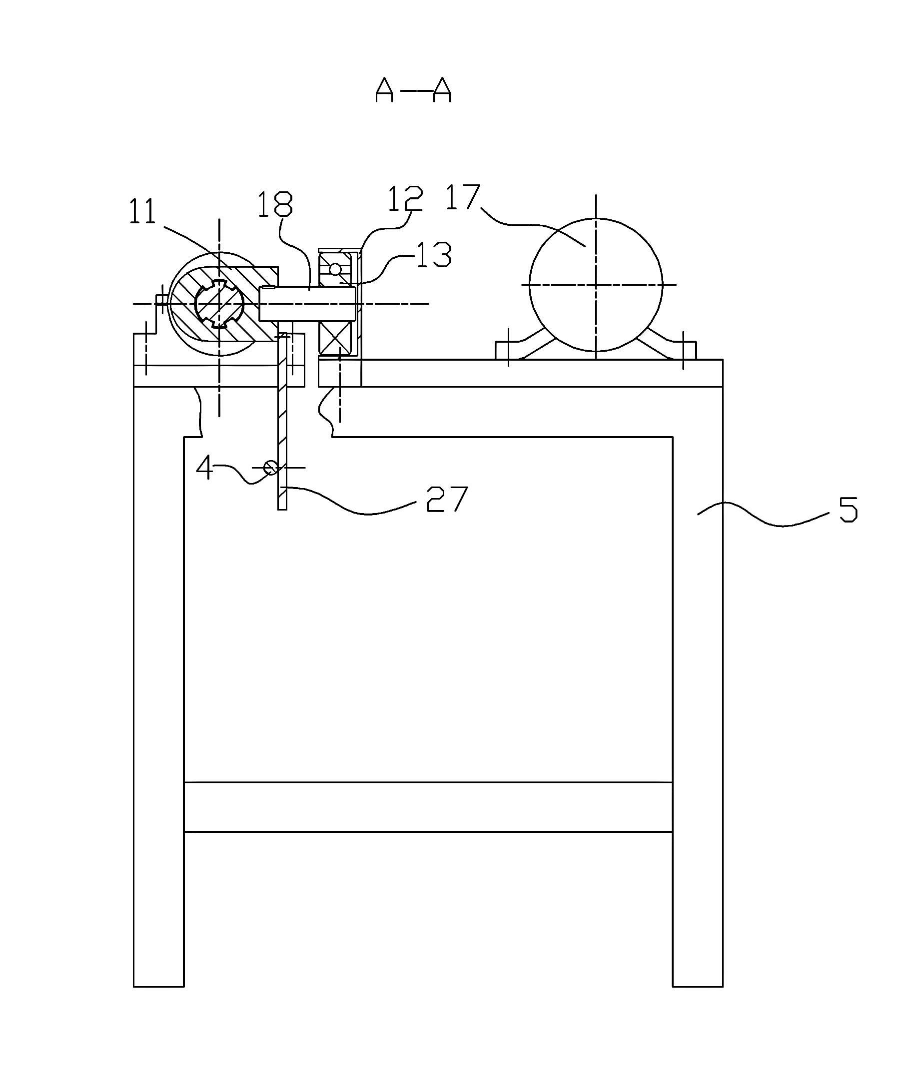
[0016] Such as figure 1 As shown, the axial center of the take-up reel 1 passes through a rotating shaft 2, and the take-up reel 1 rotates with the rotating shaft 2, and the take-up reel 1 is supported and fixed by the rotating shaft 2 through the bearing seat 6 on the frame 5. One end of the shaft 2 extending into the frame 5 is provided with a pulley 25, which combines figure 2 , Figure 4 , Figure 5 As shown, the frame 5 is provided with a reciprocating shaft 10, a transition shaft 15 and a motor 17, both ends of the reciprocating shaft 10 are supported by bearing seats 19 on the frame 5, one end of the reciprocating shaft 10 is provided with a pulley 8, and the transition shaft The two ends of 15 are supported by the bearing seats 26 on the frame 5. A sprocket 16 and a pulley 9 are arranged side by side on the transition shaft 15, and a sprocket 14 and a pulley 7 are arranged side by side on the output shaft 20 of the motor. The pulley 7 on the output shaft 20 is connected to the pulley 8 on the reciprocating shaft 10 through a belt 23, the sprocket 14 on the motor output shaft is connected to the sprocket 16 on the transition shaft 15 through a chain 22, and the pulley 9 on the transition shaft 15 The belt 21 is connected to the pulley 25 at one end of the rotating shaft 2 on the winding reel 1, and the reciprocating shaft 10 is equipped with a sliding block 11 that reciprocates along the axial direction of the reciprocating shaft 10, combining image 3 As shown, the sliding block 11 extends radially with a connecting rod 18, a rolling bearing 13 is mounted on the connecting rod 18, and a sliding groove 12 matched with the rolling bearing 13 is provided on the frame 5. The rolling bearing 13 rolls back and forth in the sliding groove 12, reciprocating A bidirectional cross spiral groove is provided on the circumferential surface of the shaft 10, and the inner wall of the slider 11 cooperates with the spiral groove, so that the slider 11 reciprocates in the axial direction on the reciprocating shaft 10. The lower part of the slider 11 is connected by a The rod 27 is connected to a reciprocating rod 24, the outer end of the reciprocating rod 24 is provided with a guide ring 4, the guide ring 4 extends out of the side of the frame 5 where the reel 1 is located, and the strip scrap 3 is passed through the guide ring 4 and then wound In the reel 1.
[0017] Working principle: The motor output shaft drives the transition shaft to rotate through a gear drive, the transition shaft drives the reel to rotate through a belt drive, the motor output shaft drives the reciprocating shaft to rotate through the belt drive, and the reciprocating shaft drives the slider to slide horizontally along its axis, sliding The block drives the reciprocating rod to make a horizontal reciprocating movement. The strip-shaped scrap 3 passes through the guide ring 4 at the outer end of the reciprocating rod and then is wound on the reel 1. Through the rotation of the reel 1 and the reciprocating movement of the reciprocating rod 28, the strip The shaped scrap 3 is wound evenly and neatly in a certain regularity in the winding reel 1.
[0018] The above-mentioned embodiments are only preferred embodiments of the present invention, which describe in detail the technical ideas and implementation points of the present invention, and are not intended to limit the scope of protection of the present invention. Any simple modification and equivalent structure made according to the spirit of the present invention All changes or modifications shall be covered by the protection scope of the present invention.

PUM

no PUM

Description & Claims & Application Information

We can also present the details of the Description, Claims and Application information to help users get a comprehensive understanding of the technical details of the patent, such as background art, summary of invention, brief description of drawings, description of embodiments, and other original content. On the other hand, users can also determine the specific scope of protection of the technology through the list of claims; as well as understand the changes in the life cycle of the technology with the presentation of the patent timeline. Login to view more.

Similar technology patents

Device for monitoring early load condition of micro-grid

PendingCN107910960Aeasy to carryeasy to reuse
Owner:天津瑞源电气有限公司

10kv outdoor transformer mounting suspender with good fixing effect

PendingCN114141513AEasy to install and transporteasy to reuse
Owner:国网河南省电力公司宜阳县供电公司 +1

Yarn rolling transporting device

InactiveCN105923026AReduce manual operationsWinding evenly
Owner:WUHU FUCHUN DYEING & WEAVING

Powdered ink filling cover

Owner:杭州达闻西科技创新有限公司

Classification and recommendation of technical efficacy words

  • easy to reuse
  • Winding evenly

Yarn rolling transporting device

InactiveCN105923026AReduce manual operationsWinding evenly
Owner:WUHU FUCHUN DYEING & WEAVING
Why Eureka
Try Eureka