
Integrated ceiling structure

A technology for integrating suspended ceilings and hanging parts, applied in ceilings, building components, building structures, etc., can solve problems such as joints and overall singleness, and achieve the effects of strong three-dimensional effect, avoiding seams, and easy production

Inactive Publication Date: 2011-12-21
湖州民普厨卫科技有限公司
View PDF9 Cites 9 Cited by
  • Summary
  • Abstract
  • Description
  • Claims
  • Application Information

AI Technical Summary

Problems solved by technology

[0002] The traditional ceiling structure includes screw hanger, main keel, triangular keel, and pinch plate. After the main keel is installed during installation, the triangular keel is connected to the main keel. The pinch plate is connected to the clipping groove of the triangular keel However, it is stable, the snap-in points are closely matched, and obvious seams are prone to appear, and the whole is single
Traditional gussets are punched by molds, and the size is precisely positioned. The production of products of different sizes requires the corresponding molds to be specially produced.

Method used


Image

  • Integrated ceiling structure
  • Integrated ceiling structure
  • Integrated ceiling structure

Examples


Embodiment 1

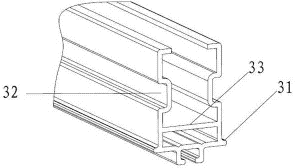
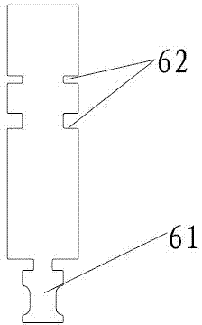
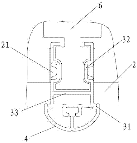
[0035] as attached figure 1 As shown in -6, an integrated ceiling structure, including main joist 1, gusset 2 and auxiliary joist 3, auxiliary joist 3 is connected with main joist 1, and the two sides of the bottom of auxiliary joist 3 are provided with pavement 31, and the two sides of the middle part are limited. Position slots 32 ; bumps 21 are provided on the buckle plate 2 ; the buckle plate 2 is placed on the pavement 31 ; the bumps 21 snap into the limiting slots 32 . A reinforcing rib 33 is arranged inside the auxiliary keel 3 . The gussets 2 are adjacently laid on two parallel auxiliary keels 3; the bottom surface of the auxiliary keels 3 is provided with a decorative strip 4. The integrated suspended ceiling also includes a keel hanger 6 through which the auxiliary keel 3 is connected to the main keel 1 . The decorative strip 4 provided at the bottom of the auxiliary keel 3 can be connected with the decorative strip 4 by way of tenon joint or slide groove.

[0036...

Embodiment 2

[0040] as attached figure 1 , 2 , 7-14, an integrated ceiling structure, including main keel 1, buckle plate 2 and auxiliary keel 3, auxiliary keel 3 is connected with main keel 1, and paving 31 is arranged on both sides of the bottom of auxiliary keel 3, and the two sides of the middle part A limiting groove 32 is provided; the pinch plate 2 is provided with a bump 21 ; the pinch plate 2 is laid on the pavement 31 ; the bump 21 is snapped into the limiting groove 32 . A reinforcing rib 33 is arranged inside the auxiliary keel 3 . The integrated suspended ceiling also includes inserts 5 arranged perpendicular to the auxiliary keel 3 . Both sides of the bottom of the cutting strip 5 are provided with ribs 51; one side of the top of the cutting strip 5 is provided with a pressure edge 52, and the other side is provided with a pressing piece 53, and the pressing piece 53 is connected with the main body of the cutting strip 5 through a bending part 54; the auxiliary keel 3 and ...


PUM


Abstract

The invention provides an integrated ceiling structure and relates to the field of decoration. The integrated ceiling structure comprises a main keel, buckle plates and auxiliary keels, wherein the auxiliary keels are connected with the main keel; paved edges are arranged at the two sides of the bottoms of the auxiliary keels; limiting grooves are arranged at the two sides of the middle parts of the auxiliary keels; bumps are arranged on the buckle plates; the buckle plates are paved on the paved edges; the bumps are clamped in the limiting grooves; reinforcing ribs are arranged inside the auxiliary keels; the buckle plates are paved on the two parallel auxiliary keels in an adjacent manner; and decorating strips are arranged on the bottom surfaces of the auxiliary keels. The integrated ceiling also comprises keel hangers, wherein the auxiliary keels are connected with the main keel by virtue of the keel hangers. The integrated ceiling is also characterized in that inserting strips are arranged between the buckle plates; retaining edges are arranged at the two sides of the bottoms of the inserting strips; pressing edges are arranged at one sides of the upper parts of the insertingstrips and pressing pieces are arranged at the other sides of the upper parts of the inserting strips; and the pressing pieces are connected with the inserting strip bodies by virtue of buckling parts. The integrated ceiling structure has the beneficial effects of simpleness and convenience in production, low production cost, good installation, strong third dimension, varied matching between shapes and colors and more beautiful whole ceiling.

Description

technical field [0001] The invention belongs to the field of decoration, and in particular relates to an integrated suspended ceiling structure. Background technique [0002] The traditional ceiling structure includes screw hanger, main keel, triangular keel, and pinch plate. After the main keel is installed during installation, the triangular keel is connected to the main keel. The pinch plate is connected to the clipping groove of the triangular keel However, it is stable, the snap-in points are closely matched, and obvious seams are prone to appear, and the whole is single. Traditional gussets are punched by dies, and the size is precisely positioned. The production of products of different sizes requires the corresponding dies to be specially produced. Contents of the invention [0003] The object of the present invention is to provide an integrated suspended ceiling structure to solve the above problems. [0004] Above-mentioned technical purpose of the present inve...

Claims


Application Information

Patent Timeline
Patent Type & Authority Applications(China)
IPC IPC(8): E04B9/00E04B9/06E04B9/12E04B9/26E04F19/06
Inventor 于爱根
Owner 湖州民普厨卫科技有限公司
Learn More