centrifugal fan

A centrifugal fan and centrifugal technology, used in mechanical equipment, non-variable-capacity pumps, machines/engines, etc., can solve the problems of high noise, high energy consumption, large air volume, etc., to increase air volume and increase air intake. area effect

Inactive Publication Date: 2011-12-21
余旦
View PDF8 Cites 9 Cited by
  • Summary
  • Abstract
  • Description
  • Claims
  • Application Information

AI Technical Summary

Problems solved by technology

[0007] Aiming at the disadvantages of large friction, high energy consumption and high noise in the prior art, the present invention provides a device that can effectively isolate and prevent the backflow of gas in the air duct without affecting the work efficiency of suction and rejection in the negative pressure area. Centrifugal fan with low noise, large air volume and small motor load

Method used


Image

  • centrifugal fan
  • centrifugal fan
  • centrifugal fan

Examples


Embodiment 1

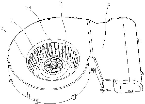
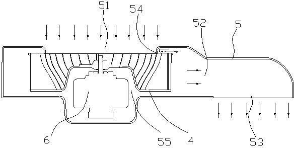
[0030] Centrifugal fans such as Figure 1 to Figure 5 It includes a volute 5, a motor 6 and a wind wheel 1 arranged on the motor 6. The wind wheel 1 includes a base 4 and a wind guide vane 2. The lower end of the wind guide vane 2 is connected to the base 4. The upper end of the wind guide vane 2 passes through the Wheel hoop 3 is fixed. A plurality of air guide vanes 2 distributed at intervals are better fastened into a whole through the tire 1 , and will not shake or twist during high-speed operation.

[0031]There are four or more wind guide vanes 2, which are evenly distributed at equal angles with the geometric center of the base 4 as the center. The wind guide blades 2 are evenly distributed and arranged symmetrically with each other, so that when the wind wheel rotates at high speed, the air volume of each wind guide blade 2 is uniform and equal.

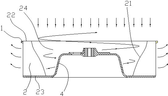
[0032] A negative pressure zone 24 is formed between the wind guide vane 2 and the base 4, the hypotenuse 21 of the wind ...


PUM


Abstract

The invention relates to a centrifugal fan, and discloses a centrifugal fan, comprising a volute (5), a motor (6) and a wind wheel (1) arranged on the motor (6), the wind wheel (1) includes a base The seat (4) is connected to the wind guide vane (2), and the lower end of the wind guide vane (2) is connected to the base (4), and the upper end of the wind guide vane (2) is fixed by the rim (3). The folded edge of the volute of the present invention cooperates with the seamless connection on the centrifugal wind guide vane, and the folded edge extends into the wind wheel. When the wind wheel rotates at a high speed in the volute, the folded edge extended into the wind wheel can effectively prevent The backflow of gas in the air duct increases the air intake area, and at the same time prevents the air pressure generated by the wind wheel from reacting on the air coming in from the air inlet, offsetting part of the air intake and increasing the air volume.

Description

technical field [0001] The invention relates to a centrifugal fan, in particular to a centrifugal fan. Background technique [0002] At present, the existing centrifugal wind wheel is formed by one-time injection molding of the base, the wind guide vane and the frame, and the shape of the front view projection surface of the wind guide vane is a simple rectangle. The defects of the existing centrifugal wind wheel are: the whole wind wheel is tough when cutting the wind, the noise is large, the energy consumption is high, the air volume is small, and the cost is high. [0003] As announced by the State Intellectual Property Office on October 28, 2009, an invention patent named "a centrifugal wind wheel" with a patent number of ZL200920112083.8 discloses a centrifugal wind wheel for a centrifugal fan. The base, the wind guide blades and the frame are injection molded at one time, the wind guide blades of the centrifugal wind wheel are arranged equidistantly along the circumfe...

Claims


Application Information

Patent Timeline
Patent Type & Authority Applications(China)
IPC IPC(8): F04D25/08F04D29/28F04D29/42
Inventor 刘丰恺
Owner 余旦
Why Eureka
Try Eureka