solid state lighting

A lighting, solid-state technology, used in fixed lighting devices, lighting devices, lighting and heating equipment, etc., can solve the problems of no display, poor circulation, and reduced heat dissipation performance.

Inactive Publication Date: 2017-09-05
深圳市秦博核芯科技开发有限公司
View PDF8 Cites 0 Cited by
  • Summary
  • Abstract
  • Description
  • Claims
  • Application Information

AI Technical Summary

Problems solved by technology

However, when the axial direction of the heat sink is placed horizontally, the heat dissipation air is not easy to flow through the surface of the fins, and there are many air flow dead zones, and the circulation is poor, so the heat dissipation performance is significantly reduced
Currently disclosed products and technologies do not show a solution to this problem

Method used


Image

  • solid state lighting
  • solid state lighting
  • solid state lighting

Examples


Embodiment Construction

[0022] specific implementation plan

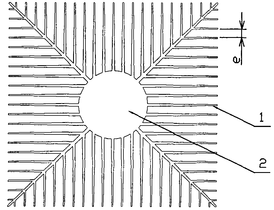
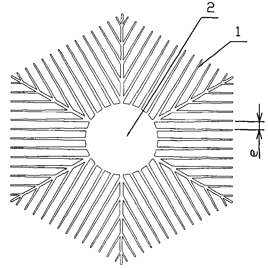
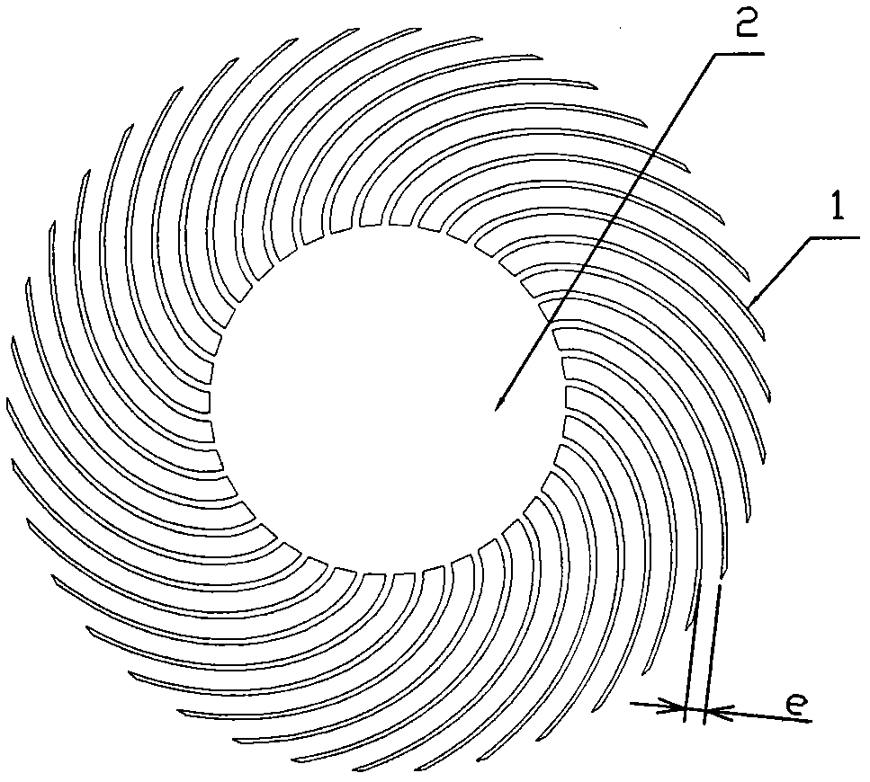
[0023] figure 1 , 2 3 and 3 show three kinds of solar fins with different shapes. The fins 1 protrude from the side of the heat conduction column 2. The heat conduction column 2 shown in the figure is solid or hollow. Using the aluminum extrusion method, the profile can be manufactured, and it can be cut to make a sun fancy heat sink. The manufacturing cost is low, and because of the high ribbing efficiency (material saving) and low internal thermal resistance, it is LED. Cooling first choice.

[0024] Figure 4 In the present invention shown, the heat conduction column 2 is solid, and the LED light source 3 is arranged on the front end surface of the heat conduction column 2. Through the contact heat transfer with the end surface, the heat of the LED light source 3 is transferred to the heat conduction column 2, and then transferred to the heat conduction column 2 by the fins 1. into the air. In the figure, rib 1 is divided into thre...


PUM


Abstract

The invention provides a solid-state lighting lamp, which includes an LED light source (3) and a heat sink. The heat sink adopts a solar fancy structure. The air flow groove (5) solves the problem of poor air circulation and serious deterioration of heat dissipation performance when the axis of the heat sink is placed horizontally. The invention also proposes an LED bulb lamp with an optimized structure size and a new structure, which can achieve lower manufacturing cost and higher heat dissipation effect.

Description

technical field [0001] The invention belongs to the technical field of LED lighting, and in particular relates to an LED lighting lamp adopting a solar fancy cooling fin. [0002] technical background [0003] Due to the advantages of energy saving and environmental protection, LED is considered to be the next generation lighting technology for human beings. However, due to the high cost and low reliability, the popularization and application of LED lighting is hindered. The main reason for the high price and unreliability is the LED heat dissipation problem. [0004] The heat dissipation temperature of LED is not high, below 100°C, so its heat dissipation mainly depends on convection heat transfer, and the proportion of radiation heat transfer is very small. In the process of convective heat transfer, the heat is finally taken away by air flow, so it is very important to ensure smooth air flow, especially natural convection heat transfer (the heat dissipation method used b...

Claims


Application Information

Patent Timeline
Patent Type & Authority Patents(China)
IPC IPC(8): F21S8/00F21V29/74F21Y115/10F21V29/83
Inventor 秦彪
Owner 深圳市秦博核芯科技开发有限公司
Why Eureka
Try Eureka