gas nozzle

A technology of gas nozzles and gas outlet pipes, applied in the field of burners, can solve problems such as low thermal efficiency and excessive CO, and achieve the effects of improving combustion efficiency, reducing CO production, and promoting mixing

Inactive Publication Date: 2011-12-21
KUNSHAN SANZHI ELECTRONICS IND
View PDF5 Cites 0 Cited by
  • Summary
  • Abstract
  • Description
  • Claims
  • Application Information

AI Technical Summary

Problems solved by technology

[0003] The structure of the existing gas nozzle itself only plays the role of transporting gas, which is insufficient

Method used


Image

  • gas nozzle
  • gas nozzle
  • gas nozzle

Examples


Embodiment Construction

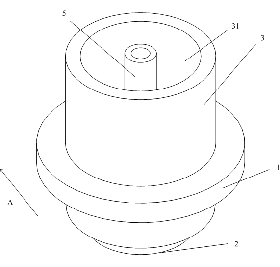
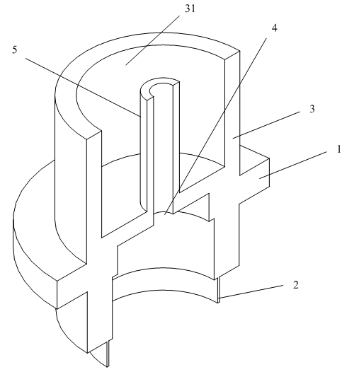
[0016] Figure 1-Figure 3 Shown is a first embodiment of a gas nozzle according to the invention. Such as figure 1 , image 3 As shown, in this embodiment, the gas nozzle 1 includes an air inlet 2 and an air outlet 4, and the inner diameter of the gas nozzle 1 gradually decreases from the air inlet 2 to the air outlet 4 in a stepwise manner. Connect with outlet pipe 5 on the top.

[0017] The wall thickness of the air outlet pipe 5 must be less than 1 / 4 of the inner diameter of the air outlet pipe 5 , that is to say less than 1 / 4 of the diameter of the air outlet 4 . Such arrangement is to ensure that the pipe wall of the air outlet pipe 5 is thin-walled to ensure the flow of air.

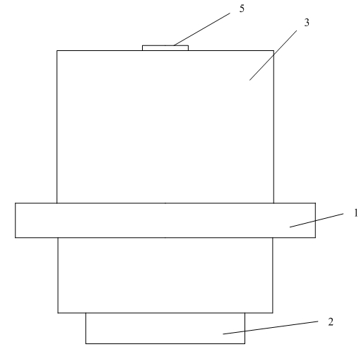
[0018] Wherein, a ring wall 3 is arranged around the air outlet pipe 5 , and a groove 31 is formed between the ring wall 3 and the air outlet pipe 5 . Such as figure 2 As shown, the air outlet end of the air outlet pipe 5 must be higher than the ring wall 3 to avoid the negative impact of th...


PUM


Abstract

The invention discloses a gas nozzle, which includes an air inlet and an air outlet. The inner diameter of the gas nozzle gradually decreases from the air inlet to the air outlet. An outlet pipe is connected to the outlet of the gas nozzle. The pipe of the outlet pipe The wall thickness is less than 1/4 inner diameter of the outlet pipe. With such a structure, when the gas is injected, it can further assist in the formation of local negative pressure, and the gas can be in contact with more air to achieve the mixing of gas and air, thereby improving the combustion efficiency and reducing the production of CO.

Description

technical field [0001] The invention relates to a burner, in particular to a gas nozzle therein. Background technique [0002] At present, the combustion method of gas appliances mostly adopts the pre-mixed air combustion method, among which, the use of gas nozzles is unavoidable. When the gas nozzle is in use, the gas is injected into the burner of the burner through the nozzle, so that a negative pressure is formed in the injection cavity of the burner, and the air is driven into the injection cavity of the burner to meet the combustion needs of the burner. [0003] The structure of the existing gas nozzle itself only plays the role of transporting gas, which is insufficient in helping the mixing of air and gas. The thermal efficiency is low, and it is easy to cause CO to exceed the standard. Contents of the invention [0004] The technical problem to be solved by the present invention is to provide a gas nozzle that increases the gas outlet flow velocity and helps to i...

Claims


Application Information

Patent Timeline
IPC IPC(8): F23D14/48
Inventor 朱明根冉以户蒋和生
Owner KUNSHAN SANZHI ELECTRONICS IND
Why Eureka
Try Eureka