
Triangular Symmetry Measuring Mechanism of Computerized Flat Knitting Machine

A detection mechanism and flat knitting machine technology, applied in the direction of measuring devices, instruments, etc., can solve the problem of low degree of generalization, achieve the same high and low position and symmetry, reduce labor intensity, and ensure the effect of quality

Inactive Publication Date: 2011-12-21
JIANGSU JINLONG TECHNOLOGY CO LTD
View PDF5 Cites 2 Cited by
  • Summary
  • Abstract
  • Description
  • Claims
  • Application Information

AI Technical Summary

Problems solved by technology

However, since this type of equipment has the exclusive characteristics of manufacturing or debugging a certain product, the degree of generalization is low, and it is often made by the mechanical product manufacturer in a tailor-made manner. The aforementioned computerized flat knitting machine triangular symmetry detection The mechanism can only be designed and produced by the manufacturer of the computerized flat knitting machine, and there is no technical inspiration for reference in the published patent or non-patent literature.

Method used


Image

  • Triangular Symmetry Measuring Mechanism of Computerized Flat Knitting Machine
  • Triangular Symmetry Measuring Mechanism of Computerized Flat Knitting Machine
  • Triangular Symmetry Measuring Mechanism of Computerized Flat Knitting Machine

Examples


Embodiment Construction

[0023] In order to enable the examiners of the patent office, especially the public, to understand the technical essence and beneficial effects of the present invention more clearly, the applicant will describe in detail the following in the form of examples, but none of the descriptions to the examples is an explanation of the solutions of the present invention. Any equivalent transformation made according to the concept of the present invention which is merely formal but not substantive shall be regarded as the scope of the technical solution of the present invention.

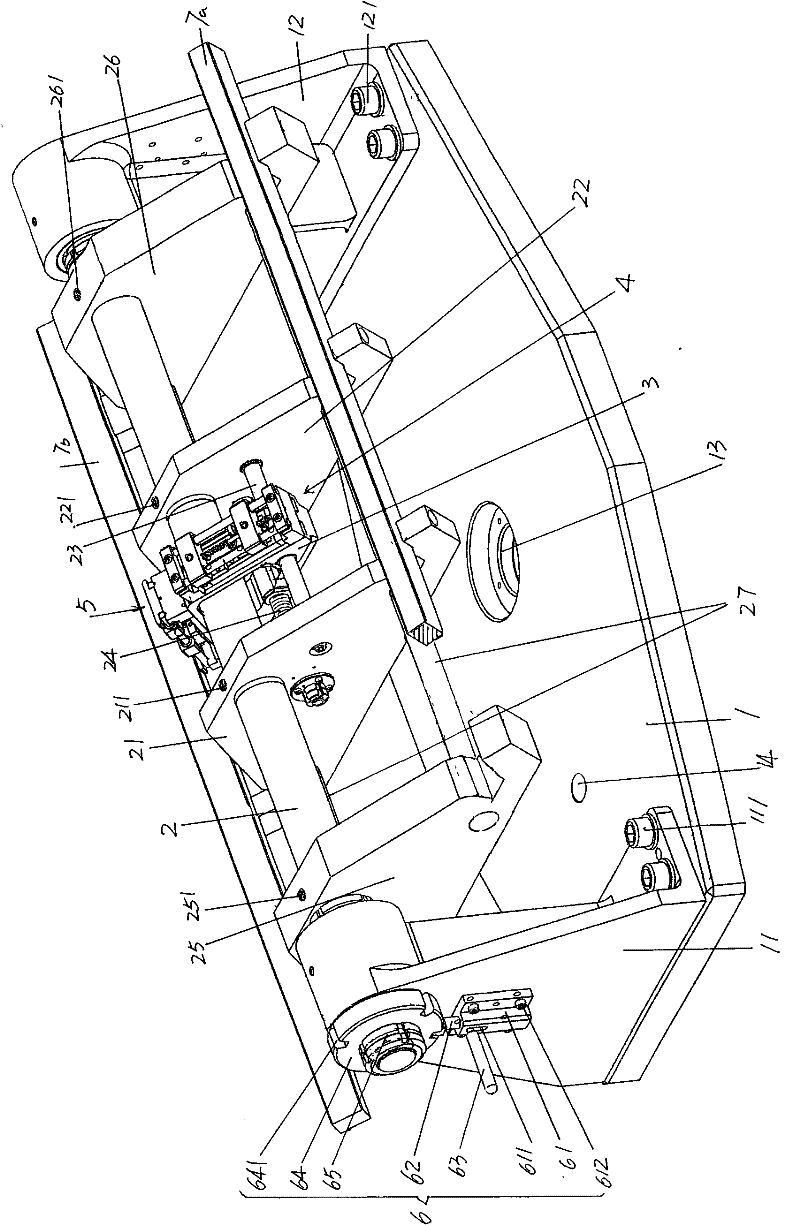
[0024] See figure 1 and figure 2 ,exist figure 1 A rotating table 1 is given in , and the rotating table 1 is placed in the Figure 4 On the adjustment machine table 9 shown, one end of the turntable 1 is figure 1 The shown left end is fixed with a group of first screws 111 with a first central shaft seat 11 in the shape of an English letter L, and at the other end of the turntable 1 is figure 1 The righ...


PUM


Abstract

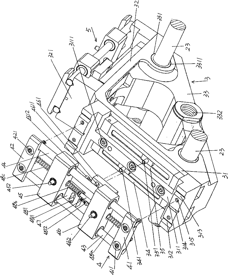
The invention relates to a triangular symmetric degree detecting mechanism for a computer flat knitting machine, belonging to the field of tools and apparatuses for assembling the computer flat knitting machine. The triangular symmetric degree detecting mechanism for the computer flat knitting machine comprises a rotating table, a central shaft, a moving base and a front machine head triangular needling trough matching device and a rear machine head triangular needling trough matching device, wherein a first central shaft seat is fixed at one end of the rotating table and a second central shaft seat is fixed at the other end of the rotating table; a rotating shaft hole is arranged on the rotating table; one end of the central shaft is supported on the first central shaft seat and the other end of the central shaft is supported on the second central shaft seat; a first supporting base and a second supporting base are fixedly arranged at a middle part of the central shaft; a pair of guide rods and a screw rod are fixed between the first supporting base and the second supporting base; the moving base consists of a first mounting body, a second mounting body and a mounting base; an upper needle trough linear displacement sensor and a lower needle trough linear displacement sensor are respectively fixed on the first mounting body and the second mounting body; the mounting base is slidingly matched with the pair of guide rods and is also matched with the screw rod; and the front machine head triangular needling trough matching device and the rear machine head triangular needlingtrough matching device are respectively fixed on the first mounting body and the second mounting body. The triangular symmetric degree detecting mechanism for the computer flat knitting machine has the advantages of increasing mounting efficiency, lowering labor intensity for mounting personnel and ensuring the quality of fabric when the triangular symmetric degree detecting mechanism is used.

Description

technical field [0001] The invention belongs to the technical field of tooling equipment for assembling a computerized flat knitting machine, and in particular relates to a triangular symmetry detection mechanism of a computerized flat knitting machine. Background technique [0002] As known in the industry, the computerized flat knitting machine has a front needle bed and a rear needle bed. The front needle bed and the rear needle bed are also called the front needle plate and the rear needle plate. Figure 8 installation, that is to say, the matching relationship between the front and rear needle beds is a figure 8 or ∧-shaped relationship when observed from the cross-sectional shape. The knitting needles arranged on the front and rear needle beds are driven by the reciprocating movement of the machine head of the knitting mechanism to complete the knitting task. The needle track of the knitting needle is reflected by the triangle on the machine head. As mentioned above, t...

Claims


Application Information

Patent Timeline
Patent Type & Authority Applications(China)
IPC IPC(8): G01B21/24
Inventor 金永良赵建生
Owner JIANGSU JINLONG TECHNOLOGY CO LTD
Learn More