Rotary stage for imaging a specimen

a rotary stage and specimen technology, applied in the direction of instruments, material analysis, measurement devices, etc., can solve the problems of affecting signal quality, difficult to introduce samples into hollow cylindrical tubes, and severe constraints on the maximum size of specimen tubes, so as to avoid specimen deflection, improve the accessibility of specimen holders, and facilitate specimen positioning

Inactive Publication Date: 2007-05-15
MEDICAL RESEARCH COUNCIL
View PDF6 Cites 38 Cited by
  • Summary
  • Abstract
  • Description
  • Claims
  • Application Information

AI Technical Summary

Benefits of technology

[0005]The rotary stage may be used with a separate microscope and associated hardware and software that allows three dimensional imaging of a specimen, such as a biological tissue. By having a specimen support means spaced from the microscope, the positioning of the specimen can be easily adjusted due to improved accessibility of the specimen holder. With an elongate specimen, the longest axis of the specimen is substantially parallel to gravity when held within the specimen support means. This allows the specimen to be held at one point only, again assisting with location of the specimen within the specimen support means, and avoids deflection of the specimen through gravitational effects, as such deflection can cause unwanted distortion of the specimen shape and affect the accuracy and resolution of the image obtained.
[0006]By having a stationary chamber separated from the rotational part of the stage, the chamber shape is not limited to a rotationally symmetric shape. Preferably the chamber has at least one planar face on which light impinges to image the specimen. Use of a flat planar face with no imperfections or undulations ensures that image distortion due to refraction of light is reduced. The chamber may be formed as a transparent hollow cuboid and arranged such that two opposing sides of the cuboid are substantially perpendicular to the optical axis along which light is emitted from the specimen so that a large cross-sectional area is presented to the optical axis. The selection of such a chamber with a square cross-section ensures that the amount of light refracted before passing through the specimen is substantially reduced over prior art cylindrical rotating chambers and thus image quality is improved. One wall or face of the chamber may be shaped so as to refract light in a desired way, for example to provide a magnifying effect.
[0011]Preferably the rotatable member is formed to enable the specimen to be hung, suspended or to downwardly depend from the lower end of the rotatable member. Where a specimen is appropriately prepared with a magnetisable metal mount, attachment of the specimen to the specimen support means is then straightforward, just relying on magnetic attraction and not on a delicate fixing. This is of advantage as typically the specimens are rather small and delicate, usually with a diameter in the range 1–20 mm, and securing them in a holder using a screw thread can be complicated.

Problems solved by technology

Light refraction from the tube affects signal quality and use of the tube places a severe constraint on the maximum size of specimen which can be imaged.
The apparatus disclosed in this prior art patent has several limitations which affect the potential uses of this imaging technique, in particular it is difficult to introduce the sample into the hollow cylindrical tube, and difficult to adjust the position of the sample.

Method used


Image

  • Rotary stage for imaging a specimen
  • Rotary stage for imaging a specimen
  • Rotary stage for imaging a specimen

Examples


Embodiment Construction

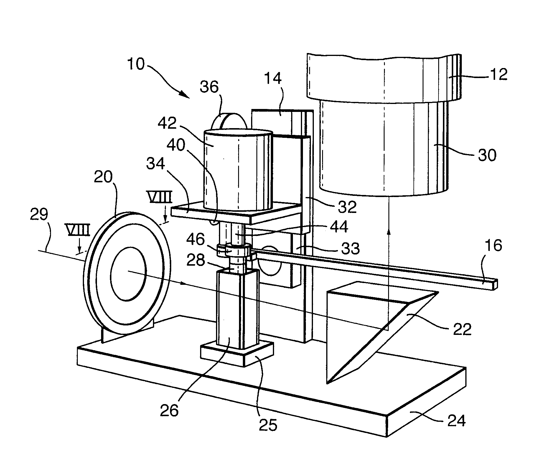
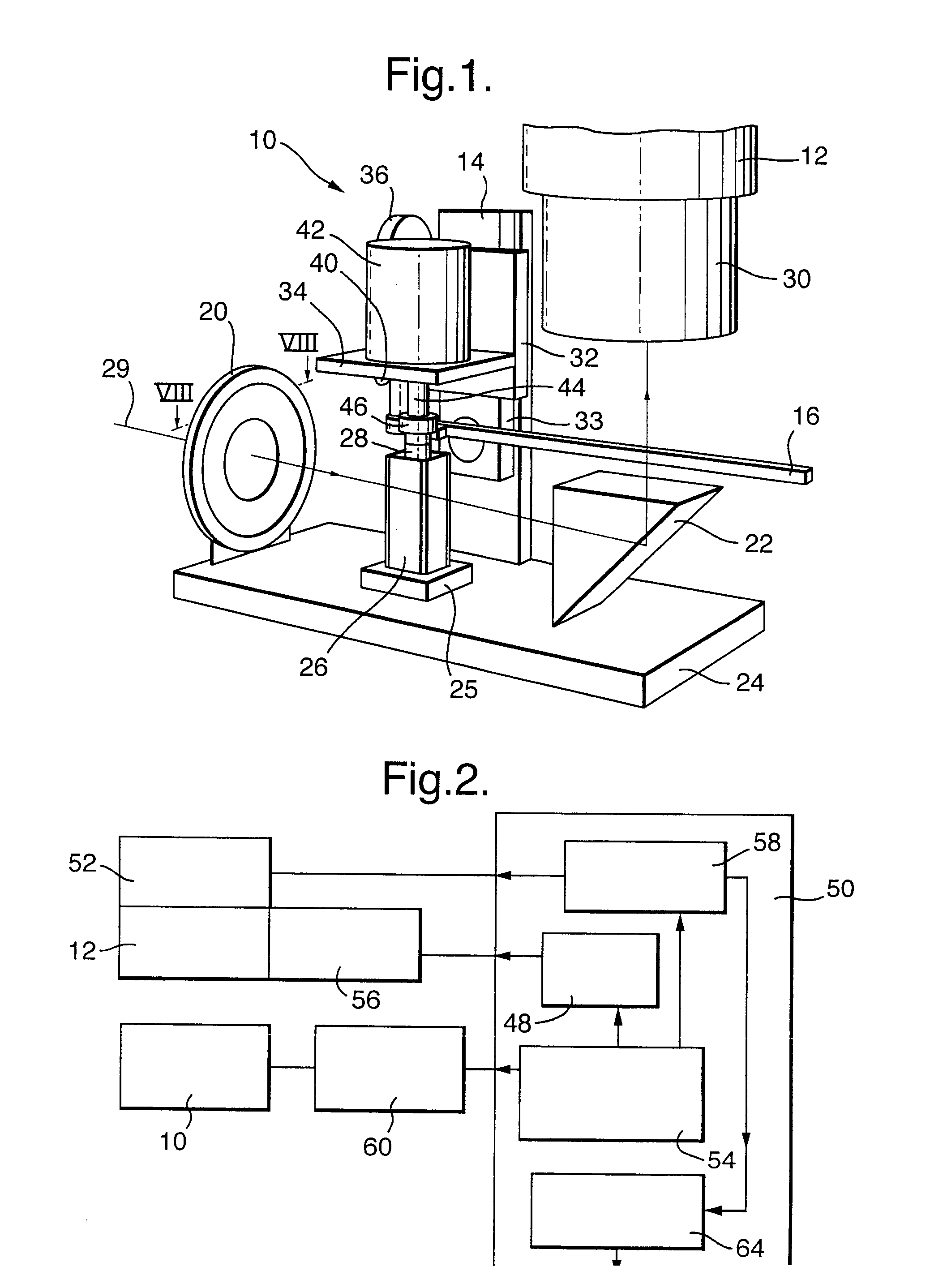
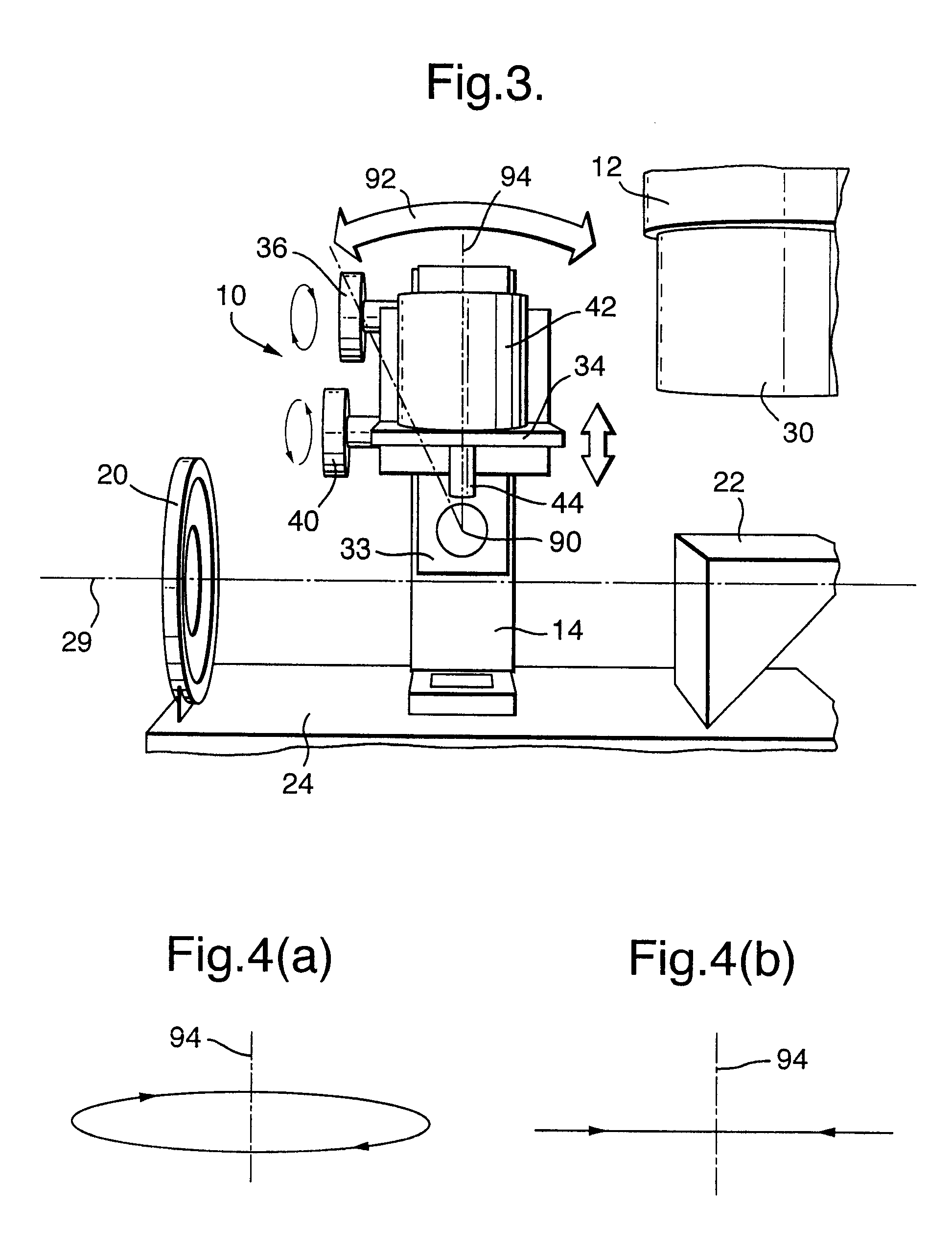
[0028]FIG. 1 shows optical imaging apparatus in the form of an OPT scanner comprising a rotary stage 10 and a long working distance or dissecting microscope 12, separate from the rotary stage 10. The rotary stage 10 has a support 14, a pivotally mounted lever 16, an iris and optical diffuser 20, and a quartz prism 22. The support 14, iris and diffuser 20, and prism 22 are fixed to a base 24 of the stage 10, as is a holder 25 for receiving a transparent chamber 26, or cuvette, of a generally cuboid shape. The cuvette 26 contains a fluid with suitable optical properties for imaging a specimen 28 suspended within the cuvette, an appropriate fluid being a mixture of benzyl alcohol and benzyl benzoate. This apparatus can be used for brightfield, darkfield and fluorescence imaging but is particularly appropriate where a three dimensional (3D) image of the specimen is created from a series of images taken at different angles, and for specimens too large to be imaged by confocal microscopy....


PUM

PropertyMeasurementUnit
angleaaaaaaaaaa
diameteraaaaaaaaaa
widthaaaaaaaaaa

Abstract

A rotary stage (10) for use in optical projection tomography includes a stepper motor (42) with a rotatable vertical shaft (44) the lower end of which carries a specimen (28) to be imaged so that the specimen is rotated about a substantially vertical axis. The stepper motor (42) is mounted on a table (34) the position of which is accurately adjustable in tilt and in vertical position to ensure that the rotational axis of the specimen is perpendicular to the optical axis (29). The specimen (28) rotates within a stationary chamber (26) and the rotary stage is used with a microscope which provides a three-dimensional image of the specimen.

Description

FIELD OF THE INVENTION[0001]This invention concerns a rotary stage for imaging a specimen, and a method of obtaining an image of a specimen. The invention is particularly, but not exclusively, concerned with optical projection tomography and three dimensional microscopy.BACKGROUND OF THE INVENTION[0002]Optical imaging apparatus for producing three-dimensional images of samples by optical projection tomography is known, see for example U.S. Pat. No. 5,680,484. The optical apparatus disclosed in this prior art patent takes a series of digital images of a sample from different angles. These images are fed into an algorithm which use a mathematical transform to reconstruct a three dimensional image. In U.S. Pat. No. 5,680,484 the specimen is held within a transparent tube which is supported at two points so as to be substantially horizontal, and the tube is rotated using a stepper motor and driving belt to allow different parts of the specimen to be imaged. Light refraction from the tub...

Claims


Application Information

Patent Timeline
Patent Type & Authority Patents(United States)
IPC IPC(8): G01N21/01G01N21/03G01N21/17G01N21/64G02B21/26G02B21/36
CPCG01N21/6458G02B21/26G02B21/367
Inventor SHARPE, JAMES ALEXANDERPERRY, PAUL ERNEST
Owner MEDICAL RESEARCH COUNCIL
Why Eureka
Try Eureka