Calibration phantom, calibration device and calibration method for calibrating geometric parameters in CT (Computed Tomography) system

A technology of geometric parameters and calibration methods, which is applied in the fields of radiological diagnostic instruments, applications, medical science, etc., can solve the problem that the geometric parameter calibration method cannot simultaneously calibrate the geometric parameters of the CT system, the parameter calibration process is complicated, and it is difficult to repeat it repeatedly. and other issues, to achieve the effect of low preparation cost, easy access, and image correction

Active Publication Date: 2013-04-03
NAT INST OF ADVANCED MEDICAL DEVICES SHENZHEN
View PDF10 Cites 40 Cited by
  • Summary
  • Abstract
  • Description
  • Claims
  • Application Information

AI Technical Summary

Problems solved by technology

[0004] However, the geometric parameter calibration method of the CT system disclosed above cannot calibrate all seven geometric parameters of the CT system at the same time; and it cannot be applied to both the ex vivo CT system (the calibration phantom rotates, the light source and the detector do not move) and in vivo CT system (the calibration phantom is fixed, the light source and the detector rotate); in addition, the parameter calibration process is more complicated, requiring multiple projections of the calibration phantom, which is difficult to implement repeatedly

Method used


Image

  • Calibration phantom, calibration device and calibration method for calibrating geometric parameters in CT (Computed Tomography) system
  • Calibration phantom, calibration device and calibration method for calibrating geometric parameters in CT (Computed Tomography) system
  • Calibration phantom, calibration device and calibration method for calibrating geometric parameters in CT (Computed Tomography) system

Examples


Embodiment 1

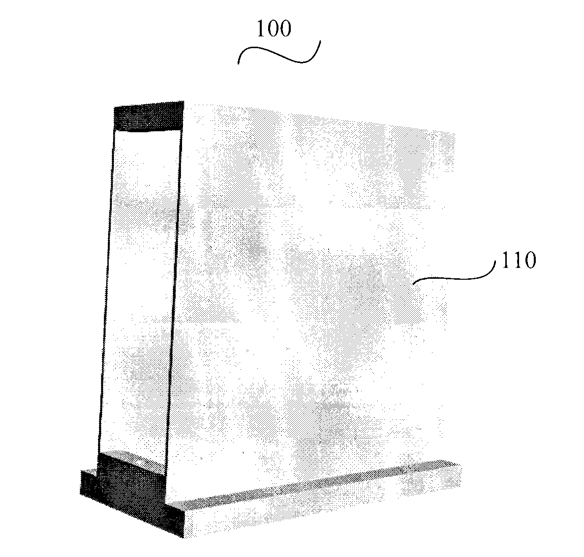
[0020] see figure 1 and figure 2 , is a schematic diagram of a calibration phantom used for calibration of geometric parameters in a CT system provided by Embodiment 1 of the present invention.

[0021] The calibration phantom 100 includes a calibration plate 110 and a small ball 120 .

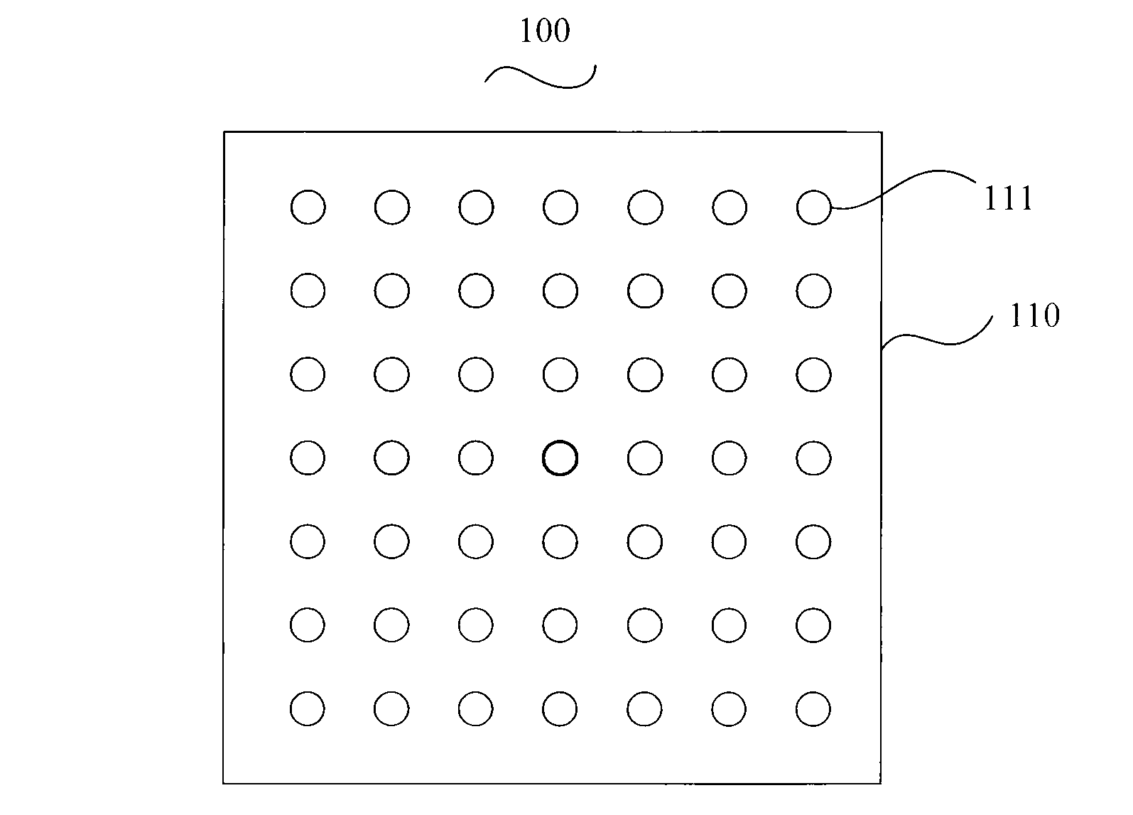
[0022] There are two calibration plates 110 with the same structure. The two calibration plates 110 are facing and arranged in parallel. In the embodiment provided by the present invention, the distance between the two calibration plates is preferably 46 mm, the width of each calibration plate is preferably 150 mm, and the thickness is preferably 2 mm. Several identical small holes 111 are correspondingly opened on the two calibration plates 110 . Small holes 111 are distributed on the calibration plate in a square matrix. see figure 2 , is a schematic diagram of the structure of the small holes 111 provided on the calibration plate 110 provided by Embodiment 1 of the present invention...

Embodiment 2

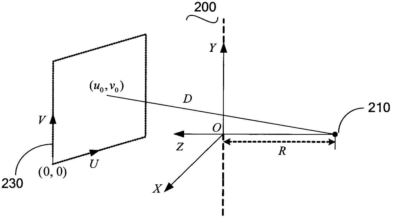
[0026] see image 3 , image 3 A schematic structural diagram of a calibration device used for calibration of geometric parameters in a CT system provided by Embodiment 2 of the present invention.

[0027] The calibration device 200 includes a CT system composed of a light source 210 , a rotating table (not shown in the figure) and a detector 230 , a calibration phantom 100 and an image processing module (not shown in the figure).

[0028] A rotating platform is provided between the light source 210 and the detector 230 . The calibration phantom 100 is vertically arranged on the rotating platform. The calibration phantom 100 rotates with the turntable. The detector 230 is used to collect the coordinates of the center point of the projected image of each small ball 120 in the small hole 111 opened on the calibration phantom 100 . It can be understood that the coordinates of the center points of the projected images of the small ball 120 on the imaging plane do not coincide....

Embodiment 3

[0031] Please also refer to image 3 and Figure 4 ,in Figure 4 The flow chart of the calibration method of geometric parameters in the CT system provided by Embodiment 3 of the present invention, wherein the CT system includes a light source 210, a rotating table and a detector 230, specifically includes the following steps:

[0032] Step S310 : Place the calibration phantom 100 vertically on the rotating platform between the light source 210 and the detector 230 . In the embodiment provided by the present invention, the calibration phantom 100 is the same as the calibration phantom provided in Embodiment 1 of the present invention. It can be understood that there are at least four small balls 120 installed in the small holes 111 on the two calibration plates 110 , that is, the small balls 120 should be placed on the two calibration plates 110 of the calibration phantom 100 .

[0033] Step S320: Rotate the calibration phantom 100 with the rotating platform, and collect th...


PUM


Abstract

The invention relates to a calibration phantom for calibrating geometric parameters in a CT (Computed Tomography) system. The calibration phantom comprises two same calibration plates which are arranged in parallel, and pellets, wherein the calibration plates are correspondingly provided with a plurality of same small holes respectively; and at least four pellets are arranged in the small holes in the calibration plates respectively. The invention relates to a calibration device for calibrating geometric parameters in a CT system. The calibration device comprises a CT system and the calibration phantom, wherein the CT system consists of a light source, a rotary platform and a detector; and the calibration phantom is vertically placed on the rotary platform between the light source and the detector. Furthermore, the invention further provides a calibration method for calibrating geometric parameters in a CT system. According to the calibration device and the calibration method, all seven geometric parameters of the CT system can be calibrated simultaneously by only performing one-time projection on the calibration phantom, so that operation is easy, and subsequent image correction of the CT system is met greatly.

Description

technical field [0001] The invention relates to the calibration of geometric parameters in a CT system, in particular to a calibration phantom, a calibration device and a calibration method for calibration of geometric parameters in a CT system. Background technique [0002] Computed tomography (CT) is an important imaging method to obtain the internal structure information of objects in a non-destructive way. It has many advantages such as high resolution, high sensitivity and multi-level, and is widely used in various medical clinical examination fields. Geometric parameter calibration is an important part of micro-CT system debugging and a prerequisite for obtaining accurate reconstructed CT images. [0003] Chinese Patent Application No. 201210148432.8 proposed "a geometric parameter calibration method for an X-ray cone-beam computed tomography system". This method uses camera calibration technology to reproduce the geometric positional relationship between the X-ray so...

Claims


Application Information

Patent Timeline
Patent Type & Authority Applications(China)
IPC IPC(8): A61B6/03
CPCA61B6/584
Inventor 胡战利郑海荣夏丹
Owner NAT INST OF ADVANCED MEDICAL DEVICES SHENZHEN
Why Eureka
Try Eureka