Foil shaping device

A technology of shaping device and foil guide strip, which is applied in the fields of capacitor manufacturing, electrical components, capacitors, etc., can solve the problems of unguaranteed quality, low efficiency and high labor intensity in shaping processing.

Inactive Publication Date: 2011-12-21
陈坤
View PDF4 Cites 6 Cited by
  • Summary
  • Abstract
  • Description
  • Claims
  • Application Information

AI Technical Summary

Problems solved by technology

[0002] In the production process of aluminum electrolytic capacitors in the traditional process, the shape arrangement of the chaff, the finalization of the position, and the placement of the finished products are all handled manually, which is labor-intensive and low-efficiency; The quality of processing is not guaranteed

Method used


Image

  • Foil shaping device
  • Foil shaping device
  • Foil shaping device

Examples


Embodiment 1

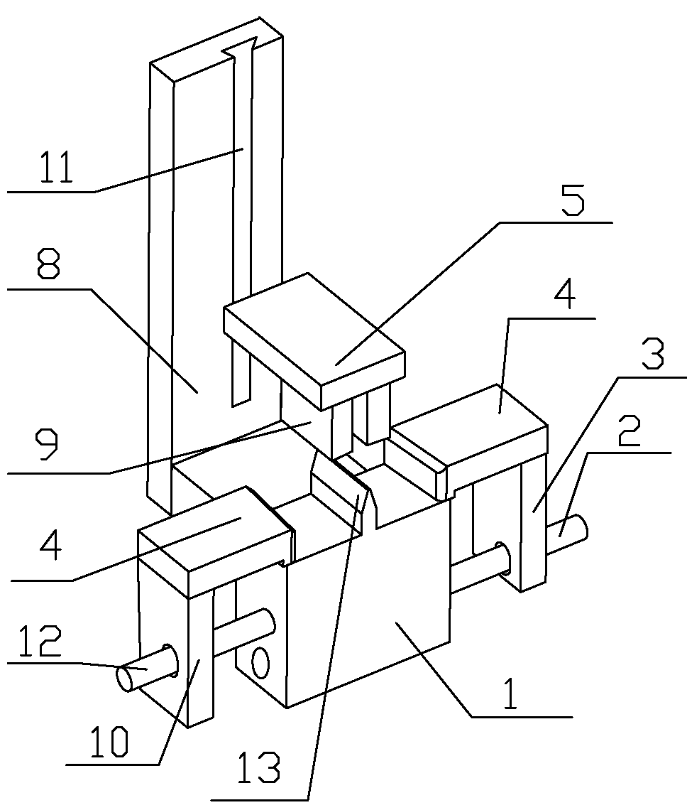
[0040] Such as figure 1As shown, the guide chaff shaping device includes a correcting bottom mold 1, an upper correcting mold arranged on the top of the correcting bottom mold 1, two horizontally correcting flat molds and a vertically arranged fixing plate 8; The middle part of the end face is provided with a protruding elongation direction as a bump 13 in the front and rear direction, and the correction bottom mold 1 is fixed on the lower end of the front side of the fixed plate 8; the upper correction mold includes a fixed block 5 and two correction blocks 9, The correction block 9 is fixed on the lower end surface of the fixed block 5 in parallel, and there is a channel between the two correction blocks 9, the elongation direction of the channel is the front and rear direction and the channel is connected with the bump 13 on the upper end of the correction bottom mold 1 In cooperation, the rear end of the fixed block 5 is provided with a boss (not shown in the figure), and...

Embodiment 2

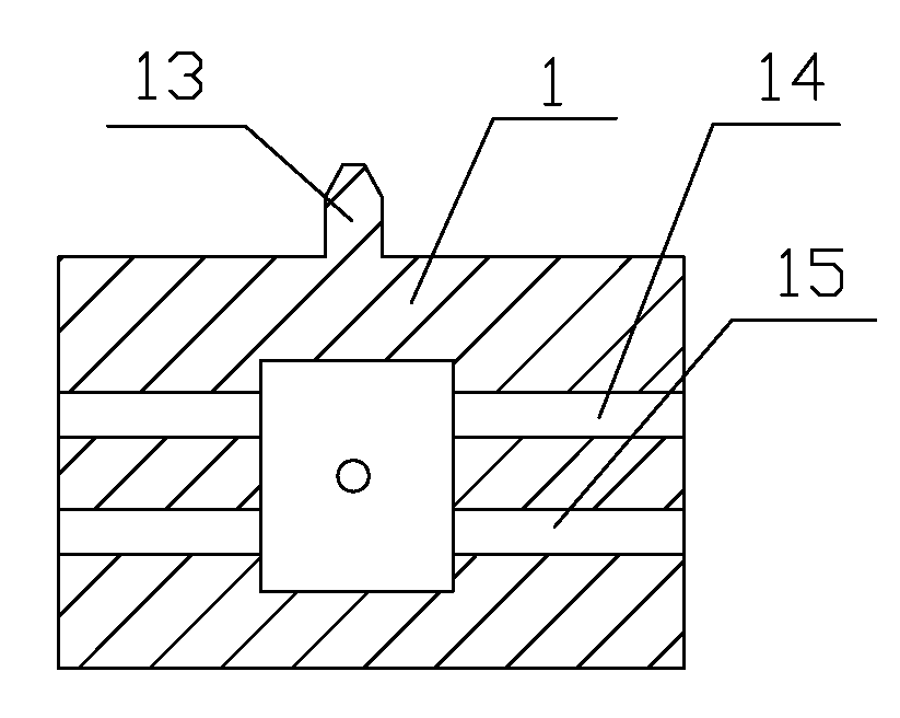
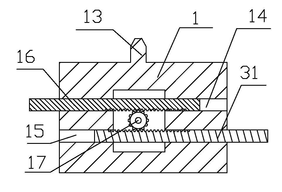
[0046] Such as figure 2 , 3 As shown, the structure of the guide chaff shaping device is basically the same as that of Embodiment 1, the difference is that: the middle part of the rear side of the corrected bottom mold 1 has an installation groove, and the left guide post 12 and the right guide post 2 are up and down. Setting, the lower end face of left guide post 12 is provided with lower rack, the upper end face of right guide post 2 is provided with upper rack, is provided with gear 17 in the mounting groove, and gear 17 meshes with lower rack, upper rack respectively.

[0047] The left guide post 12 and the right guide post 2 are meshed with the gear 17 respectively, so the movement of the left guide post 12 and the right guide post 2 is synchronized, and only one of the left guide post 12 or the right guide post 2 needs to be driven to move to drive the two. A synchronous movement can save the transmission device, simplify the device and reduce the cost.

Embodiment 3

[0049] Such as Figure 4 As shown, the structure of the guide chaff shaping device is basically the same as that of Embodiment 2, the difference is that: the upper end of the fixing plate 8 is fixed with a U-shaped block 18, and a guide is formed between the two sides of the U-shaped block 18. Groove 11; the boss is nested in the guide groove 11.

[0050] The U-shaped block 18 is used to form the guide groove 11, and the procedure of processing the guide groove 11 on the fixing plate 8 is omitted, which is simple, convenient and practical.

[0051] Further, the front side of the U-shaped block 18 is provided with a cover plate 6, and the boss extends upwards to form a slider 7, the upper end of the slider 7 stretches out from the U-shaped block 18, and the lower end of the slider 7 is connected to the upper correction mold. The rear end of the fixed block 5 is connected.

[0052] The cover plate 6 cooperates with the U-shaped block 18, so that the slider 7 can only move up a...


PUM


Abstract

The invention relates to a conductive chaff shaping device which comprises a bottom correction die, an upper correction die, two horizontal correction flat dies and a fixing plate; the middle part of the upper end surface of the bottom correction die is provided with a lug, and the bottom correction die is fixed at the lower end part of the fixing plate; the upper correction die comprises a fixing block and two correction blocks; the correction blocks are fixed at the lower end surface of the fixing block; a groove channel is arranged between the two correction blocks; the fixing block is provided with a boss, and the fixing plate is provided with a guide groove; each horizontal correction flat die comprises a horizontal correction block; the two horizontal correction flat dies are respectively positioned above the left side and the right side of the bottom correction die; the horizontal correction flat dies at two sides are respectively provided with a left connecting block and a right connecting block; the left connecting block and the right connecting block are respectively connected with a left guide post and a right guide post; the bottom correction die is provided with a left groove channel and a right groove channel; one end of the left guide post is fixed on the left connecting block, and the other end of the left guide post is positioned in the left groove channel; and one end of the right guide post is fixed on the right connecting block, and the other end of the right guide post is positioned in the right groove channel. The shaping device provided by the invention has a simple structure, and is labor saving and cost saving.

Description

technical field [0001] The invention relates to the technical field of production equipment for aluminum electrolytic capacitors, in particular to a chaff shaping device. Background technique [0002] In the production process of aluminum electrolytic capacitors in the traditional process, the shape arrangement of the chaff, the finalization of the position, and the placement of the finished products are all handled manually, which is labor-intensive and low-efficiency; The quality of processing is not guaranteed. Contents of the invention [0003] The invention solves the deficiencies of the prior art, and provides an automatic chaff shaping device. The chaff shaping device automatically performs shaping processing on the chaff leading. The chaff shaping quality is high, manpower is saved, and production efficiency is improved. [0004] The technical scheme adopted in the present invention is: [0005] The foil guide shaping device comprises a correcting bottom mold, a...

Claims


Application Information

Patent Timeline
Patent Type & Authority Applications(China)
IPC IPC(8): H01G13/00
Inventor 陈坤
Owner 陈坤
Why Eureka
Try Eureka