motor actuator

A technology of actuators and motors, which is applied in the direction of electric components, casings/covers/supports, and mechanical energy control, to achieve the effect of simple structure and difficult vibration

Inactive Publication Date: 2011-12-21
TOKYO PARTS IND CO LTD
View PDF6 Cites 8 Cited by
  • Summary
  • Abstract
  • Description
  • Claims
  • Application Information

AI Technical Summary

Problems solved by technology

[0005] However, in the motor actuator described in Patent Document 1, since a part of the motor is housed in contact with the motor housing recess 109 provided on the bottom surface of the case main body 101 and the cover 102, the vibration when the motor rotates is easily transmitted to the case. body and cover

Method used


Image

  • motor actuator
  • motor actuator
  • motor actuator

Examples


Embodiment Construction

[0018] Hereinafter, embodiments of the present invention will be described by way of example based on the drawings. However, materials, shapes, relative arrangements, and the like of components described in this embodiment are not intended to limit the scope of the present invention to these unless otherwise specified.

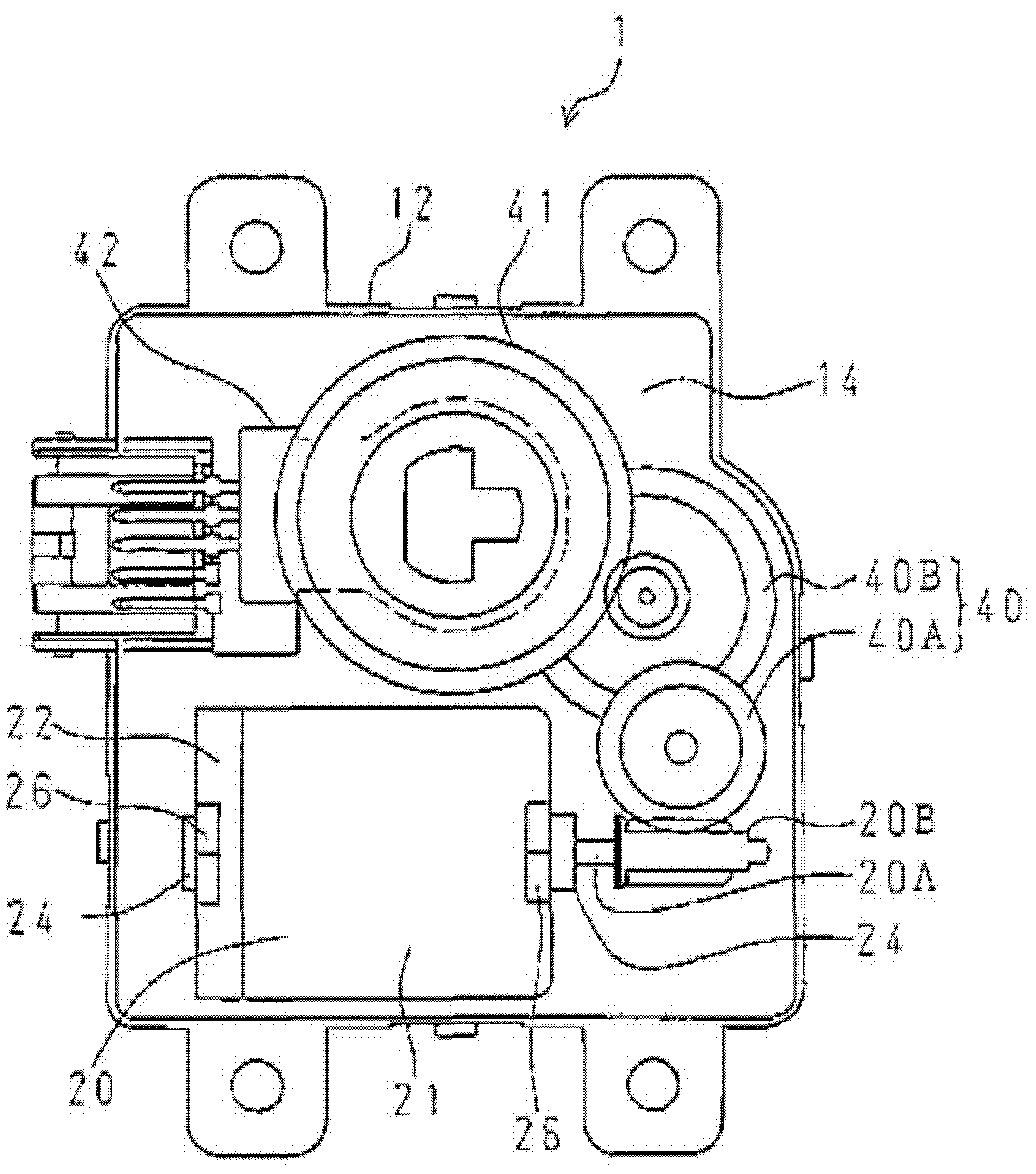
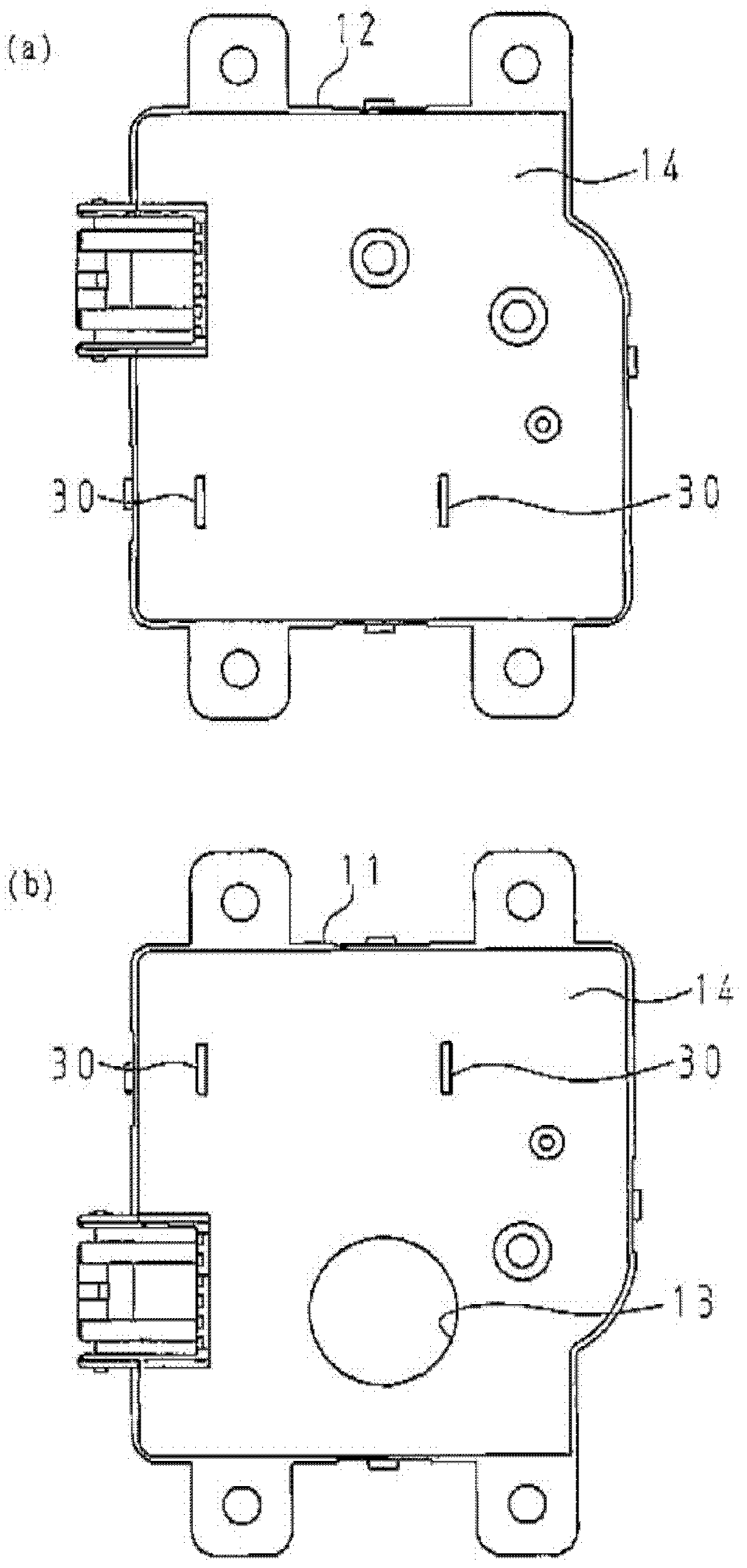
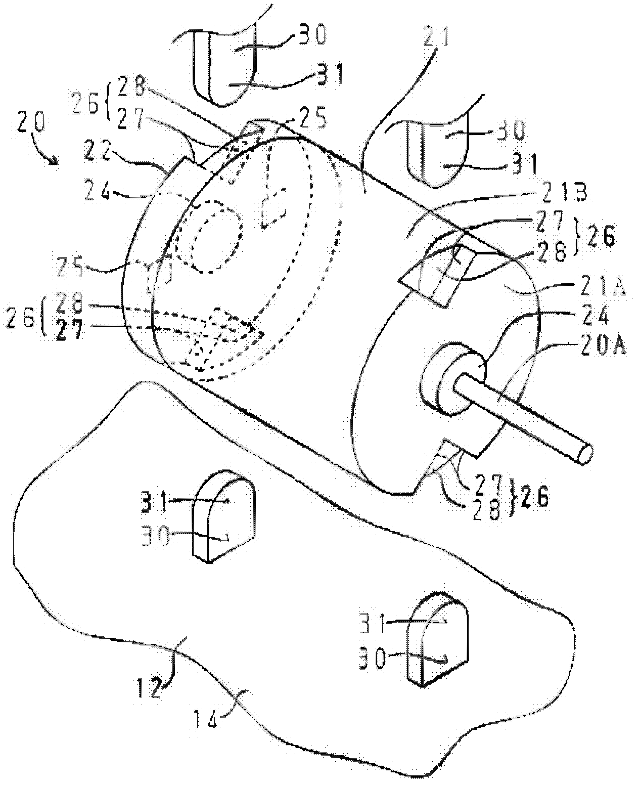
[0019] figure 1 It is a plan view of the motor actuator excluding the upper case according to one embodiment of the present invention. figure 2 (a) is figure 1 A top view of the lower shell, figure 2 (b) is figure 1 A top view of the upper shell. image 3 Yes figure 1 A perspective view of the assembly near the motor. Figure 4 Viewed from the direction of the axis of rotation, the figure 1 A side view of the upper and lower case when the motor is inside. Figure 5 is configured in figure 1 Front view of the motor inside the upper and lower housings.

[0020] like Figure 1 to Figure 5 As shown, the motor actuator 1 of this example is used i...


PUM


Abstract

Provided is a motor actuator which prevents the rotation of a motor by using a simple structure, and the vibration of the motor is not easy to transfer to a casing. A motor (20) disposed in the upper and lower casings (11,12) of the motor actuator is provided with a motor casing (21) and a motor casing cover (22), and the bottom (21A) of the motor casing and the motor casing cover (22) are respectively provided with two recessed portions (26). The recessed portions (26) clamp the rotating shaft of the motor (2) and are disposed above and below the assembling direction of the upper and lower casings (11,12), the inner sides of the upper and lower casings (11,12) are respectively provided with two motor support portions (3) composed of vertical rib plates. The two motor support portions (30) of the lower casing (12) are fastened with the recessed portions (26) below, the two motor support portions (30) of the upper casing (11) are fastened with the recessed portions (26) above, and the motor in non-contact with the bottom surfaces of the upper and lower casing is supported.

Description

technical field [0001] The present invention relates to a mounting structure of a motor of a motor actuator. Background technique [0002] A motor actuator driven by a motor is known as a drive source for an air damper valve of an air-conditioning apparatus used in a vehicle such as an automobile (for example, Patent Document 1). [0003] The motor actuator as Figure 7 As shown, a motor 104 having a rotating shaft 103 is accommodated inside a housing formed by assembling a case main body 101 and a cover 102 . The bearing accommodating portion 105 of the motor 104 is directly sandwiched by the motor support portion 106 provided at the case main body 101 and the cooperative support portion 107 provided at the cover 102 . Furthermore, in order to prevent the rotation of the motor 104, the rotation prevention support part 108 which abuts on the motor 104 is uprightly provided in the inner surface of a case. [0004] Patent Document 1: Japanese Patent Laid-Open No. 2009-201325...

Claims


Application Information

Patent Timeline
Patent Type & Authority Applications(China)
IPC IPC(8): H02K7/10H02K5/04H02K5/24
Inventor 小柳尚久渡边裕司
Owner TOKYO PARTS IND CO LTD
Why Eureka
Try Eureka