A method and device for reporting cache status reports and determining data volume

A technology for caching status reporting and data volume, applied in digital transmission systems, network traffic/resource management, error prevention/detection using return channels, etc., and can solve problems such as large differences in data volume

Active Publication Date: 2011-12-21
DATANG MOBILE COMM EQUIP CO LTD
View PDF4 Cites 42 Cited by
  • Summary
  • Abstract
  • Description
  • Claims
  • Application Information

AI Technical Summary

Problems solved by technology

[0044] The technical problem to be solved by the present invention is to provide a method and device for reporting the cache status report and determining the data volume, so as to solve the problem of how to Issues of reporting BSR and determining the amount of data to be sent

Method used


Image

  • A method and device for reporting cache status reports and determining data volume
  • A method and device for reporting cache status reports and determining data volume
  • A method and device for reporting cache status reports and determining data volume

Examples


example 1

[0123] Image 6 It is a schematic diagram of the R / R / E / LCID subheader. Taking this figure as an example, the MAC CE format can be implemented as follows: the MAC CE format remains unchanged, and the subheader represents Table information.

[0124] 1) Among them, the RR field is jointly coded to represent the Table Index. If the UE does not use more than 2 Tables, only one of the R bits can be used to indicate the Table;

[0125] 2) Use the reserved LCID to indicate that the BSR contains the BSR MAC CE of the BS Table information, where the RR bit is used to indicate the specific Table Index;

[0126] 3) Use the reserved LCID to directly indicate the BS Table information.

example 2

[0128] The MAC CE format can be implemented as follows: Table Index information is introduced into the MAC CE format, and the subheader indicates the new BSR MAC CE.

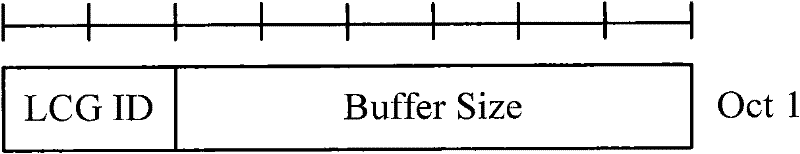
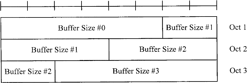
[0129] Figure 7 It is a schematic diagram of the Long BSR sub-header, Figure 8 It is a schematic diagram of the Short / Truncated BSR subheader. Taking this figure as an example, the R bit or reserved LCID in the MAC subheader indicates that it is a new BSR MAC CE. The format of the new BSR MAC CE can be as follows Figure 7 , Figure 8 Shown:

[0130] Mode 2: Each LCG indicates the new BSR MAC CE of the BSR Table respectively.

[0131] 1. Use the reserved R bits in the BSR MAC CE subheader, or the reserved LCID to indicate the new BSRMAC CE format;

[0132] 2. For the Buffer Size of each LCG, the Table Index is displayed.

[0133] Image 6 It is a schematic diagram of the R / R / E / LCID subheader. Taking this figure as an example, in the MAC CE subheader, the R bit in the subheader can be used to indicate tha...

Embodiment 1

[0138] Currently, CA UE is only configured with one LCG. When UE reports BSR, it selects the BSR Table according to the amount of data to be sent by the LCG, and uses the reserved R bits in the BSR MAC CE header to indicate the used BSR Table. The BSR reported at this time is only the Short BSR.


PUM


Abstract

The invention discloses a method for reporting a buffer status report, a method for determining quantity of data and equipment. The method for reporting the buffer status report comprises the following steps of: determining quantity of data to be transmitted of each logical channel bank by user equipment; determining a buffer status report table and buffer size according to the quantity of the data to be transmitted of each logical channel bank; carrying a buffer status report table number and a buffer size number of each logical channel bank in a buffer status report media access control unit; and reporting the buffer status report media access control unit to a network side. The invention provides a scheme which is suitable for a multi-carrier system and is used for selecting from a plurality of buffer status report tables and buffering the status report based on the information of each logical channel bank; and thus, the problems of ways to buffer the status report and determine the quantity of the data to be transmitted under the conditions of availability of a plurality of buffer status reports and large difference in size of the quantity of data of different logical channel banks are solved.

Description

technical field [0001] The invention relates to mobile communication, in particular to a method and device for reporting buffer state reports and determining data volume. Background technique [0002] 1. Carrier aggregation [0003] The peak rate of LTE-A (Long Term Evolution-Advance, long-term evolution upgrade) is greatly improved compared with LTE (Long Term Evolution, long-term evolution), and it is required to reach 1Gbps in the downlink and 500Mbps in the uplink. At the same time, the LTE-A system requires good compatibility with the LTE system, and the maximum bandwidth of the LTE system is 20MHz. The LTE-A system introduces a CA (Carrier Aggregation, Carrier Aggregation) technology based on the need to increase the peak rate, be compatible with the LTE system, and make full use of frequency resources. [0004] The carrier aggregation technology refers to the uplink and downlink of a cell containing multiple CCs (Component Carriers, component carriers), instead of o...

Claims


Application Information

Patent Timeline
Patent Type & Authority Applications(China)
IPC IPC(8): H04L1/00H04L1/16H04W28/06H04W72/12
Inventor 许芳丽赵亚利谌丽
Owner DATANG MOBILE COMM EQUIP CO LTD
Why Eureka
Try Eureka