Lighting equipment, lamp, lighting circuit, and lighting device

A technology of lighting equipment and equipment, which is applied in the field of lamps, lighting circuits, lighting devices, and lighting equipment, can solve problems such as inconsistent maintenance, and achieve the effect of reliable reset

Inactive Publication Date: 2011-12-21
PANASONIC CORP
View PDF6 Cites 5 Cited by
  • Summary
  • Abstract
  • Description
  • Claims
  • Application Information

AI Technical Summary

Problems solved by technology

As a result, the luminaire cannot light new lamps at the proper dimming ratio, and thus cannot consistently maintain the light output from the lamps

Method used


Image

  • Lighting equipment, lamp, lighting circuit, and lighting device
  • Lighting equipment, lamp, lighting circuit, and lighting device
  • Lighting equipment, lamp, lighting circuit, and lighting device

Examples


no. 1 example

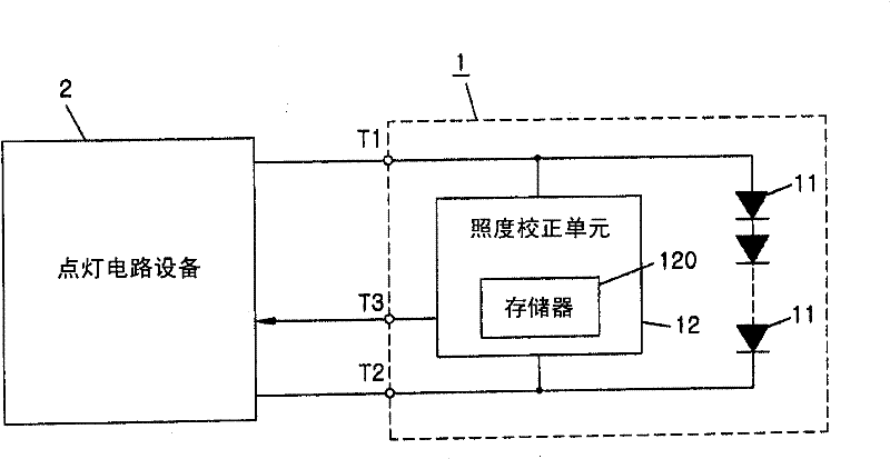
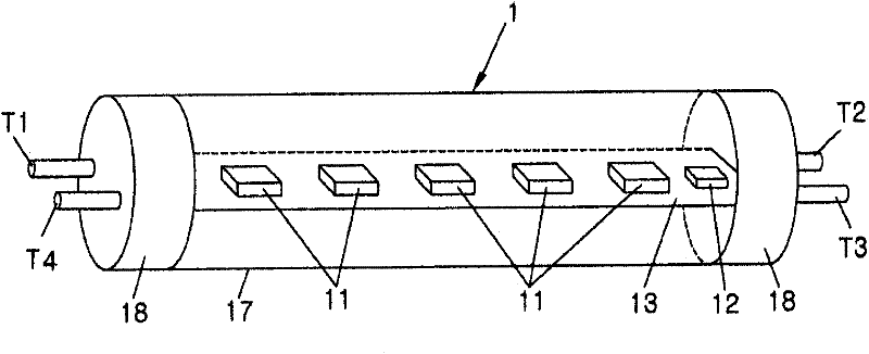
[0034] Such as figure 1 As illustrated, the lighting device according to the first embodiment of the present invention includes a lamp 1 and a lighting circuit 2 . The lamp 1 is configured to be replaceable and comprises one or more light emitting elements 11 .

[0035] The lighting circuit 2 includes a lighting device and lights the lamp 1 by supplying power to the light emitting element 11 provided inside the lamp 1 and the lighting device including a flyback DC-DC converter. In addition to the light emitting element 11, the lamp 1 also includes an illuminance correction unit 12 having a memory 120, which will be described in detail later. Here, the term "light emitting element" refers to an element that receives power and then emits light, such as a light emitting diode (LED) or an organic electroluminescent (EL) device. In the present embodiment, an LED is used as the light emitting element 11 .

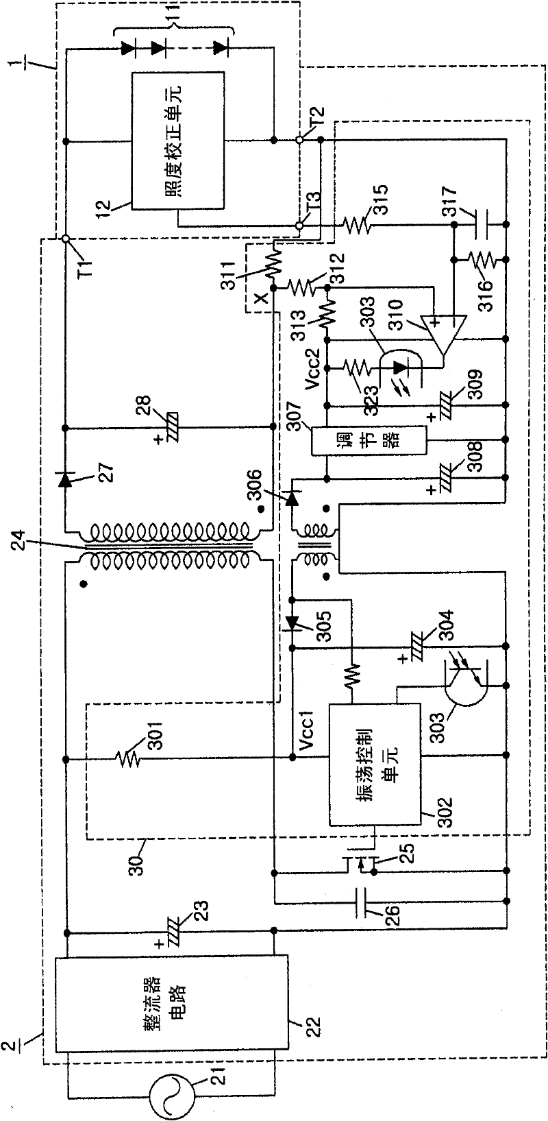
[0036] Such as figure 2 As shown, the lighting circuit 2 includes a rec...

no. 2 example

[0083] The lighting device according to the second embodiment differs from the lighting device of the first embodiment in that, as Figure 10 As shown, a step-down chopper type converter (step-down chopper circuit) is used in the lighting device of the lighting circuit 2 . Therefore, descriptions of the same configuration and functions of the present embodiment as those of the first embodiment will be omitted here, and only descriptions of configurations and functions of the current embodiment different from those of the first embodiment will be given below.

[0084] In the step-down chopper circuit, a series circuit of a switching element 31 and a diode 32 is connected in parallel to the smoothing capacitor 23, and the switching element 31 is formed of a MOSFET. In the current embodiment, the cathode of the diode 32 is connected to the positive electrode of the smoothing capacitor 23 via the switching element 31 . A series circuit of a choke coil 33 and a capacitor 34 is con...

no. 3 example

[0101] The lighting device of the third embodiment is different from the lighting device of the second embodiment in that, as Figure 12 As shown, the second lamp 1b including a general fluorescent lamp and the first lamp 1a including a light emitting element (for example, LED) 11 may be used together as the lamp. In the present embodiment, the lamp 1b is constituted by a straight tube fluorescent lamp, and the lamps 1a and 1b have a common appearance.

[0102] For the lighting circuit 2 of the current embodiment and the description in conjunction with the second embodiment Figure 11 The basic configuration of the lighting circuit 2 is common. In the present embodiment, the lighting circuit 2 includes the second switching element 35 formed of a MOSFET instead of Figure 11 Diode 32 is shown. When the lighting device operates as a step-down chopper circuit, by fixing the gate-source of the second switching element 35 to "low level", a parasitic diode (not shown) embedded in...


PUM


Abstract

A lighting device comprising: a replaceable lamp including at least one light-emitting element; a lighting device for lighting the light-emitting element by supplying power to the lamp; and a device for performing dimming control on the lamp. Illumination correction unit. The illuminance correction unit includes a timer for counting an accumulated light emitting time of the light emitting element and a memory for storing the accumulated light emitting time counted by the timer. The illuminance correcting unit determines the dimming ratio of the light emitting element based on the accumulated luminous time stored in the memory and an illuminance correction characteristic, wherein the accumulated luminous time and the dimming of the light emitting element are determined The relationship between the ratios is such that the light output from the light emitting element is consistently maintained even when the accumulated light emitting time is increased. The memory is provided in the lamp.

Description

technical field [0001] The present invention relates to a lighting device, a lamp, a lighting circuit, and a lighting device capable of consistently maintaining light output from a lamp despite an increase in cumulative luminous time. Background technique [0002] In order to compensate for a decrease in light output due to aging of fluorescent lamps or pollution due to long-term use, there has been disclosed a lighting device configured to cumulatively count the lighting time and perform dimming control so that the dimming The light ratio can increase proportionally with the cumulative luminescence time. This type of luminaire is able to prevent degradation of light output due to aging degradation, for example by setting the initial value of the dimming ratio to 70% of the rated value and gradually increasing the dimming ratio as the cumulative luminous time increases, thereby essentially Consistently maintains light output from fluorescent lamps. [0003] Also, recently,...

Claims


Application Information

Patent Timeline
Patent Type & Authority Applications(China)
IPC IPC(8): H05B37/02H05B44/00
CPCH05B33/0815H05B33/0854H05B45/58H05B47/20H05B45/18H05B45/385H05B45/375
Inventor 光安启滨本胜信
Owner PANASONIC CORP
Why Eureka
Try Eureka