Ultrasonic diagnostic device

A diagnostic device, ultrasonic technology, applied in the direction of blood flow measurement device, echo tomography, etc.

Inactive Publication Date: 2011-12-21
KONICA MINOLTA INC
View PDF6 Cites 10 Cited by
  • Summary
  • Abstract
  • Description
  • Claims
  • Application Information

AI Technical Summary

Problems solved by technology

[0021] The object of the present invention is to solve the problems in the prior art, and to provide a diagnostic device that can clearly distinguish changes in blood flow at diagnostic sites such as the carotid artery where the blood flow velocity changes rapidly, and even in the blood flow velocity An ultrasonic diagnostic device capable of displaying smooth blood flow motion images without image loss even at low

Method used


Image

  • Ultrasonic diagnostic device
  • Ultrasonic diagnostic device
  • Ultrasonic diagnostic device

Examples


no. 1 approach

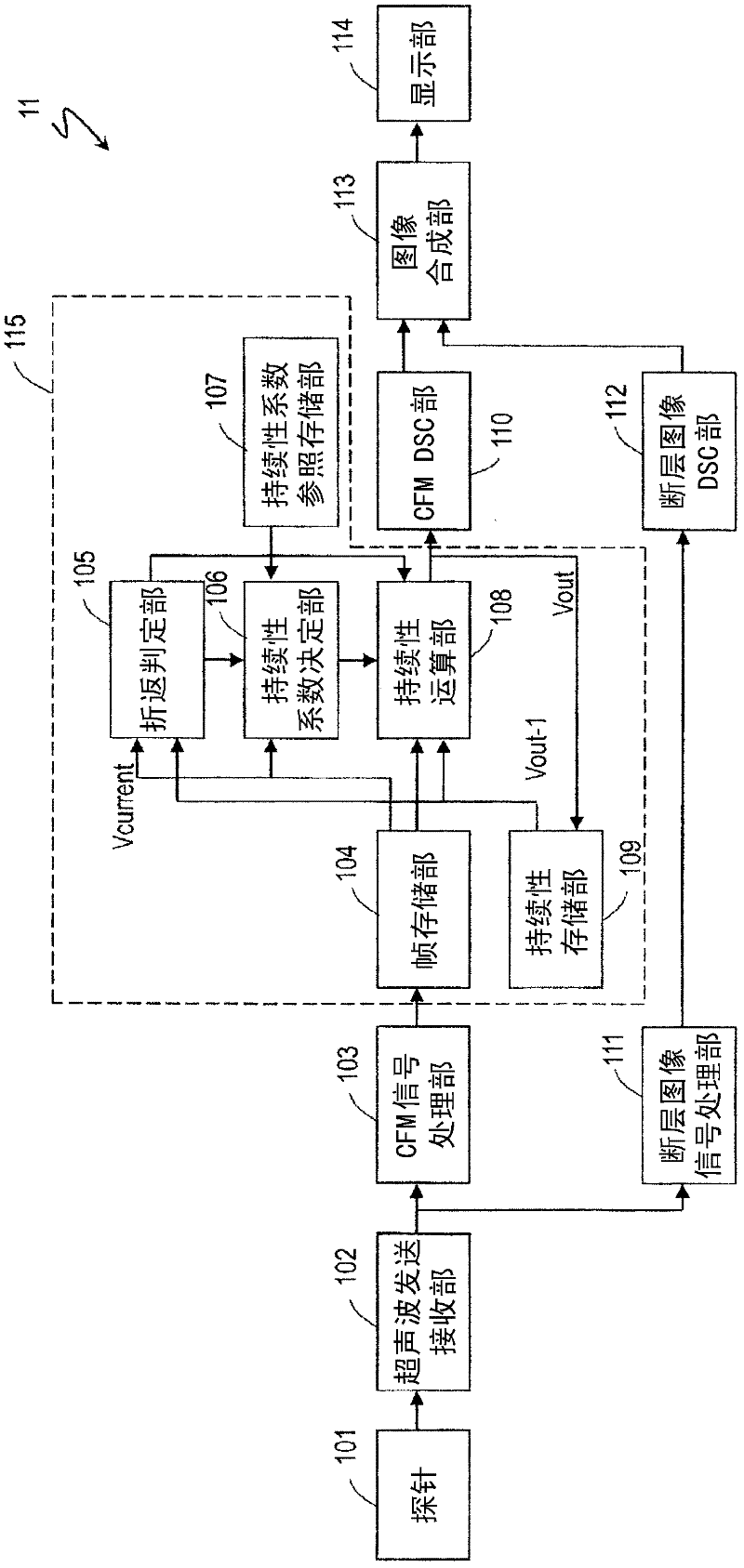
[0044] Hereinafter, a first embodiment of the ultrasonic diagnostic apparatus of the present invention will be described with reference to the drawings. figure 1 It is a block diagram showing the first embodiment of the ultrasonic diagnostic apparatus of the present invention. figure 1 The illustrated ultrasonic diagnostic apparatus 11 has: a probe 101, an ultrasonic transmitting and receiving unit 102, a CFM signal processing unit 103, an afterimage processing unit 115, a tomographic image signal processing unit 111, a CFM DSC unit 110, a tomographic image DSC unit 112, an image Combining unit 113 and display unit 114 . In these configurations, general-purpose probes and display devices can be used for the probe 101 and the display unit 114 , and the ultrasonic diagnostic apparatus 11 may not have the probe 101 and the display unit 114 .

[0045] The ultrasonic transmitter / receiver 102 generates a drive signal for driving the probe 101 and outputs the drive signal to the p...

no. 2 approach

[0093] Hereinafter, a second embodiment of the ultrasonic diagnostic apparatus of the present invention will be described with reference to the drawings. Figure 4 It is a block diagram showing an embodiment of the ultrasonic diagnostic apparatus of the present invention. Figure 4 The illustrated ultrasonic diagnostic apparatus 12 includes: a probe 101, an ultrasonic transmitting and receiving unit 102, a CFM signal processing unit 103, an afterimage processing unit 115′, a tomographic image signal processing unit 111, a CFM DSC unit 110, a tomographic image DSC unit 112, An image synthesis unit 113 and a display unit 114 . In these configurations, general-purpose probes and display devices can be used for the probe 101 and the display unit 114 , and the ultrasonic diagnostic apparatus 12 may not have the probe 101 and the display unit 114 .

[0094] As described in the first embodiment, the ultrasonic transmitter-receiver 102 generates a drive signal for driving the probe 1...


PUM


Abstract

Disclosed is an ultrasonic diagnostic device, provided with: a transmitting / receiving unit which repeatedly drives a probe, receives through the probe reflected echoes obtained as the ultrasound wave transmitted by means of driving the probe reflects off a subject, and sequentially generates a plurality of receiving signals; a color flow mapping signal processing unit which sequentially generates blood flow rate data of the blood flow portion of the subject's body for each frame on the basis of the plurality of received signals; a remaining image processing unit which processes the remaining images for each frame with respect to the blood flow rate data; a tomographic image signal processing unit which generates a B-mode tomographic image frame data on the basis of the receiving signals; and an image synthesizing unit which synthesizes the blood flow rate data that was processed by the remaining image processing unit and the B-mode tomographic image frame data. The remaining image processing unit performs a folding assessment on the basis of the blood flow rate data of the newest frame and the blood flow rate data that was processed by the remaining image processing unit of the frames before the newest frame and dynamically changes the coefficient of persistence on the basis of the results of the folding assessment and the blood flow rate data of the newest frame and the frames therebefore.

Description

technical field [0001] The invention relates to an ultrasonic diagnostic device, in particular to an afterimage processing method during color blood flow imaging. Background technique [0002] An ultrasonic diagnostic apparatus generates an image inside a subject by transmitting ultrasonic waves to the subject and analyzing information contained in reflected echoes. The blood flow in the subject can also be visualized by a method called Color Flow Mapping (hereinafter sometimes abbreviated as CFM), and it is widely used in all medical fields. Ultrasonic diagnostic device for flow state. [0003] Color flow imaging is also called color Doppler imaging (Color Doppler Imaging, CDI), which utilizes the Doppler effect. When the blood flow is irradiated with ultrasonic waves, due to the Doppler effect, a Doppler shift corresponding to the blood flow velocity occurs in the reflected echo. This Doppler shift information is detected by quadrature detection, and high-pass filter pr...

Claims


Application Information

Patent Timeline
Patent Type & Authority Applications(China)
IPC IPC(8): A61B8/06
CPCA61B8/06A61B8/13
Inventor 右田学
Owner KONICA MINOLTA INC
Why Eureka
Try Eureka