Objective lens and optical pickup device
A technology for an optical pickup device and an objective lens, which can be applied to beam guiding devices, optical recording heads, recording/reproducing by optical methods, etc., can solve the problems of rising cost, disadvantageous miniaturization, etc., to ensure the working distance and reduce the paraxial Effect of curvature radius, long focus distance
- Summary
- Abstract
- Description
- Claims
- Application Information
AI Technical Summary
Problems solved by technology
Method used
Image
Examples
Embodiment 1
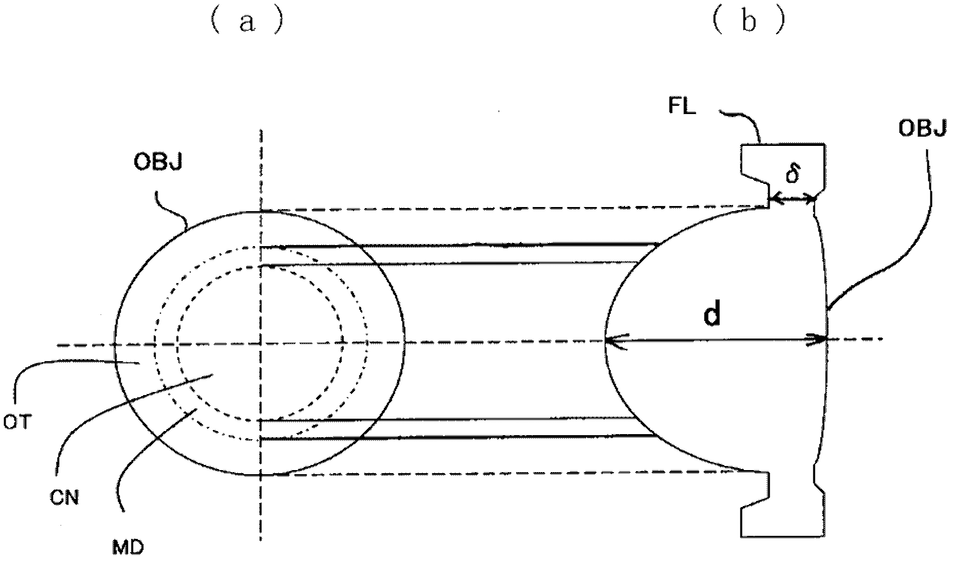
[0239] Table 1 shows the lens data of Example 1. Image 6 It is a sectional view of the objective lens of Example 1. Figure 7 (a) is a schematic diagram of longitudinal spherical aberration (solid line) and sinusoidal condition (dashed line) of Example 1 when used in BD, Figure 7 (b) is a schematic diagram of longitudinal spherical aberration (solid line) and sine condition (dashed line) when DVD is used in embodiment 1, Figure 7 (c) is a schematic diagram of longitudinal spherical aberration (solid line) and sinusoidal condition (dotted line) of Example 1 when used in CD. In embodiment 1, such as Image 6 As shown in the enlarged diagram of , the first area R1 including the optical axis is a BD / DVD shared area, the second area R2 around it is a CD-only area, and the third area R3 around it is a BD / DVD shared area. The fourth area R4 around the outside is a CD-only area, the fifth area R5 around it is a BD / DVD shared area, and the sixth area R6 farthest from the optical ...
Embodiment 2
[0249] Figure 8 It is a sectional view of the objective lens of Example 2. Figure 9 (a) is a schematic diagram of longitudinal spherical aberration (solid line) and sinusoidal condition (dashed line) of Example 2 when used in BD, Figure 9 (b) is a schematic diagram of longitudinal spherical aberration (solid line) and sine condition (dashed line) when DVD is used in embodiment 2, Figure 9 (c) is a schematic diagram of longitudinal spherical aberration (solid line) and sinusoidal condition (dotted line) of Example 2 when CD is used. Embodiment 2 adopts the lens data of Embodiment 1, and has the same number of regions, but different region division positions. Other points, including the numerical value of the formula, are the same as in Example 1, and description thereof will be omitted.
Embodiment 3
[0251] Figure 10 It is a sectional view of the objective lens of Example 3. Embodiment 3 is different from Embodiment 1 and 2 in that it is a lens with 4 regions, such as Figure 10 As shown in the enlarged diagram of , the first region R1 including the optical axis is a BD / DVD shared area, the second area R2 around it is a CD-only area, and the third area R3 around it is a BD / DVD shared area , the fourth region R4 whose outer periphery is farthest from the optical axis is a BD-only region. Figure 11 (a) is a schematic diagram of longitudinal spherical aberration (solid line) and sinusoidal condition (dashed line) of Example 3 when used in BD, Figure 11 (b) is a schematic diagram of longitudinal spherical aberration (solid line) and sinusoidal condition (dashed line) of embodiment 3 when DVD is used, Figure 11 (c) is a schematic diagram of longitudinal spherical aberration (solid line) and sinusoidal condition (dotted line) of Example 3 when CD is used. Embodiment 3 ad...
PUM
| Property | Measurement | Unit |
|---|---|---|
| thickness | aaaaa | aaaaa |
| thickness | aaaaa | aaaaa |
| refractive index | aaaaa | aaaaa |
Abstract
Description
Claims
Application Information
 - R&D Engineer
- R&D Manager
- IP Professional
- Industry Leading Data Capabilities
- Powerful AI technology
- Patent DNA Extraction
Browse by: Latest US Patents, China's latest patents, Technical Efficacy Thesaurus, Application Domain, Technology Topic, Popular Technical Reports.
© 2024 PatSnap. All rights reserved.Legal|Privacy policy|Modern Slavery Act Transparency Statement|Sitemap|About US| Contact US: help@patsnap.com


