
Pay-off device

A pay-off rack and rack device technology, applied in the field of pay-off rack devices, can solve problems such as wire breakage, and achieve the effect of avoiding breakage and simple structure

Inactive Publication Date: 2011-12-28
江苏宏泰不锈钢丝绳有限公司
View PDF0 Cites 0 Cited by
  • Summary
  • Abstract
  • Description
  • Claims
  • Application Information

AI Technical Summary

Problems solved by technology

In the process of unwinding, if a knotted steel wire is encountered, the unwinding will be blocked. When the tension exceeds a certain value, the steel wire will be broken. The pay-off stand device that can cut off the power immediately and stop the pay-off

Method used


Image

  • Pay-off device
  • Pay-off device
  • Pay-off device

Examples


Embodiment Construction

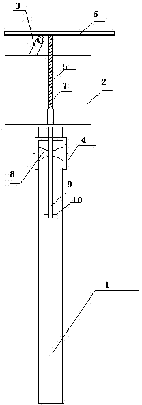
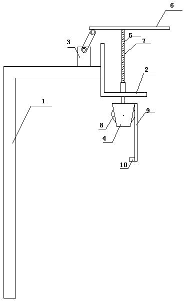
[0012] Such as figure 1 , as shown in 2, a pay-off stand device of the present invention includes a bracket 1, a bracket 2 is fixed at one end of the bracket 1, and a travel switch 3 is arranged beside the bracket 2, wherein the travel switch 3 is fixed on On the support 1; a roller frame 4 is provided below the bracket 2, and a vertical central axis 5 passes through the bracket 2, and its top end is fixed on the iron plate 6, and its bottom end is fixed on the On the roller frame 4, a spring 7 is sleeved on the central shaft 5; a roller 8 is fixed in the roller frame 4, wherein a groove is arranged on the circumference of the roller 8.

[0013] The pay-off stand device also includes an iron rod 9 , one end of which is fixed on the roller frame 4 , and the other end is connected with an incoming coil 10 , and the incoming coil 10 is located below the roller frame 4 .

[0014] The pay-off stand device of the present invention has a simple structure. When the steel wire is p...


PUM


Abstract

The invention discloses a wire pay-off stand device, the wire prevention stand device includes a bracket, a bracket is fixed at one end of the bracket, and a travel switch is arranged beside the bracket, wherein the travel switch is fixed on the bracket ; A roller frame is arranged below the bracket, a vertical central axis passes through the bracket, its top end is fixed on the iron plate, and its bottom end is fixed on the roller frame. A spring is covered; a roller is fixed in the roller frame. As a further improvement of the present invention, a groove is provided on the circumference of the roller; the pay-off stand device also includes an iron rod, one end of which is fixed on the roller frame, and the other end is connected with an incoming coil. The coil is located under the roller frame. The pay-off device of the invention has a simple structure and can prevent the steel wire from being broken.

Description

technical field [0001] The invention relates to a pay-off rack device. Background technique [0002] Nowadays, in the process of producing steel wire rope, the steel wire should be put into the steel wire cleaning machine to clean the oil stain on the surface, so the wound steel wire should be straightened through the pay-off frame and sent to the steel wire cleaning machine for cleaning. In the process of unwinding, if a knotted steel wire is encountered, the unwinding will be blocked. When the tension exceeds a certain value, the steel wire will be broken. A pay-off stand device that can cut off the power immediately and stop the pay-off. Contents of the invention [0003] The purpose of the present invention is to provide a kind of pay-off device that can cut off the power supply immediately when the pay-off is found to be blocked during the pay-off process, so as to avoid the wire rope from being pulled off. [0004] To achieve the above object, the present invent...

Claims


Application Information

Patent Timeline
IPC IPC(8): B21C47/18
Inventor 陈爱红董德元王存金赵五平徐春林
Owner 江苏宏泰不锈钢丝绳有限公司
Features
  • Generate Ideas
  • Intellectual Property
  • Life Sciences
  • Materials
  • Tech Scout
  • Unparalleled Data Quality
  • Higher Quality Content
  • 60% Fewer Hallucinations
Learn More