
Center hole positioning wheel set press machine

A positioning wheel and center hole technology, applied in metal processing, metal processing equipment, manufacturing tools, etc., can solve the problems of imperfection and imperfection, and achieve the effect of simplifying the structure, simplifying the control part, and reducing the cost.

Active Publication Date: 2011-12-28
HUBEI HEQIANG MACHINERY DEV LIMITED BY SHARE
View PDF5 Cites 4 Cited by
  • Summary
  • Abstract
  • Description
  • Claims
  • Application Information

AI Technical Summary

Problems solved by technology

So far, although there have been many patented products of pressing and unloading machines, which meet the market needs after the train speed is increased, they are still not perfect enough and not ideal.

Method used


Image

  • Center hole positioning wheel set press machine
  • Center hole positioning wheel set press machine
  • Center hole positioning wheel set press machine

Examples


Embodiment Construction

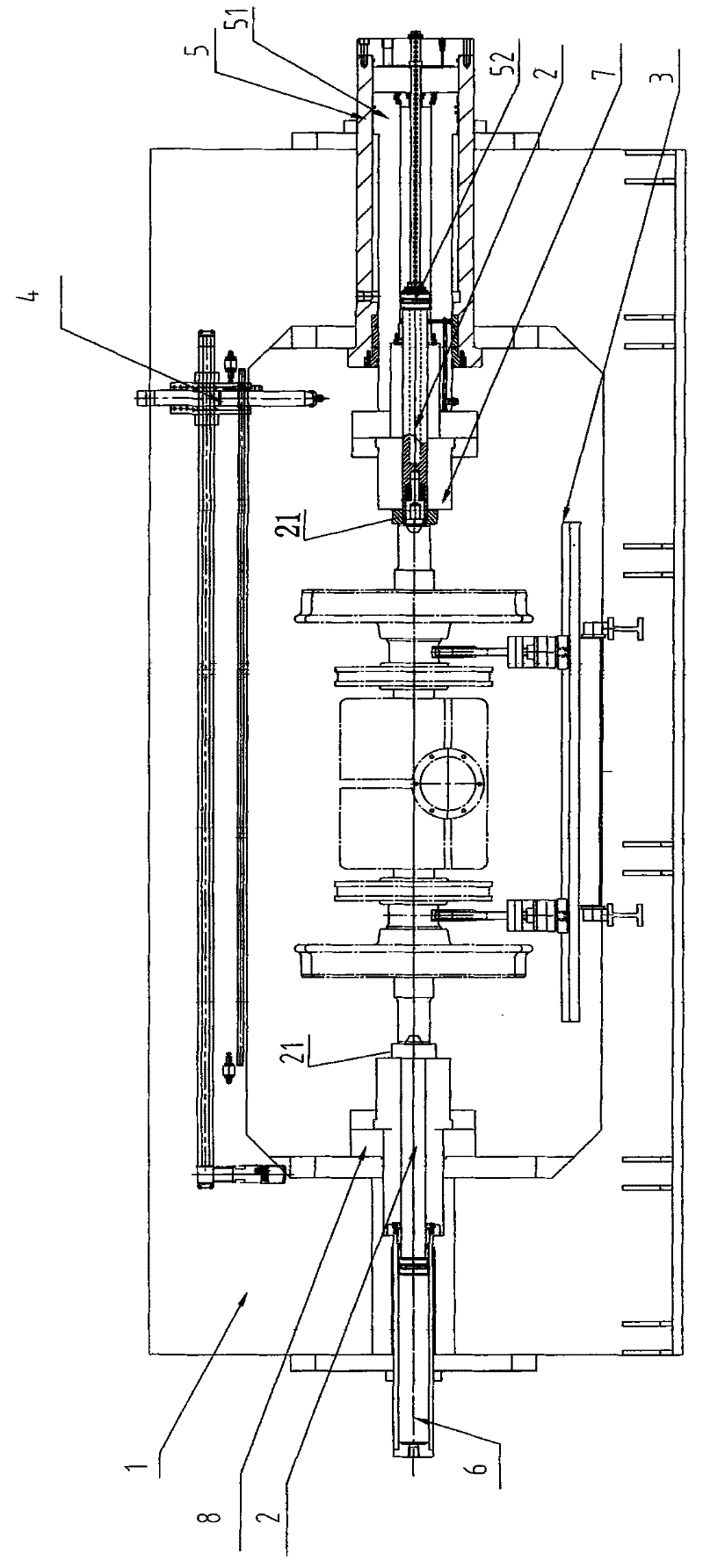
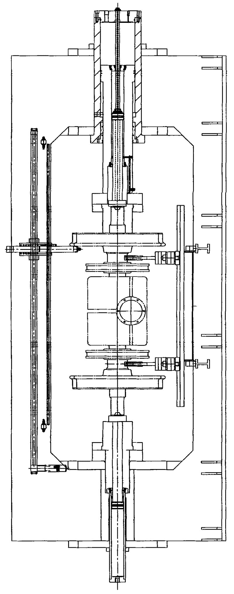
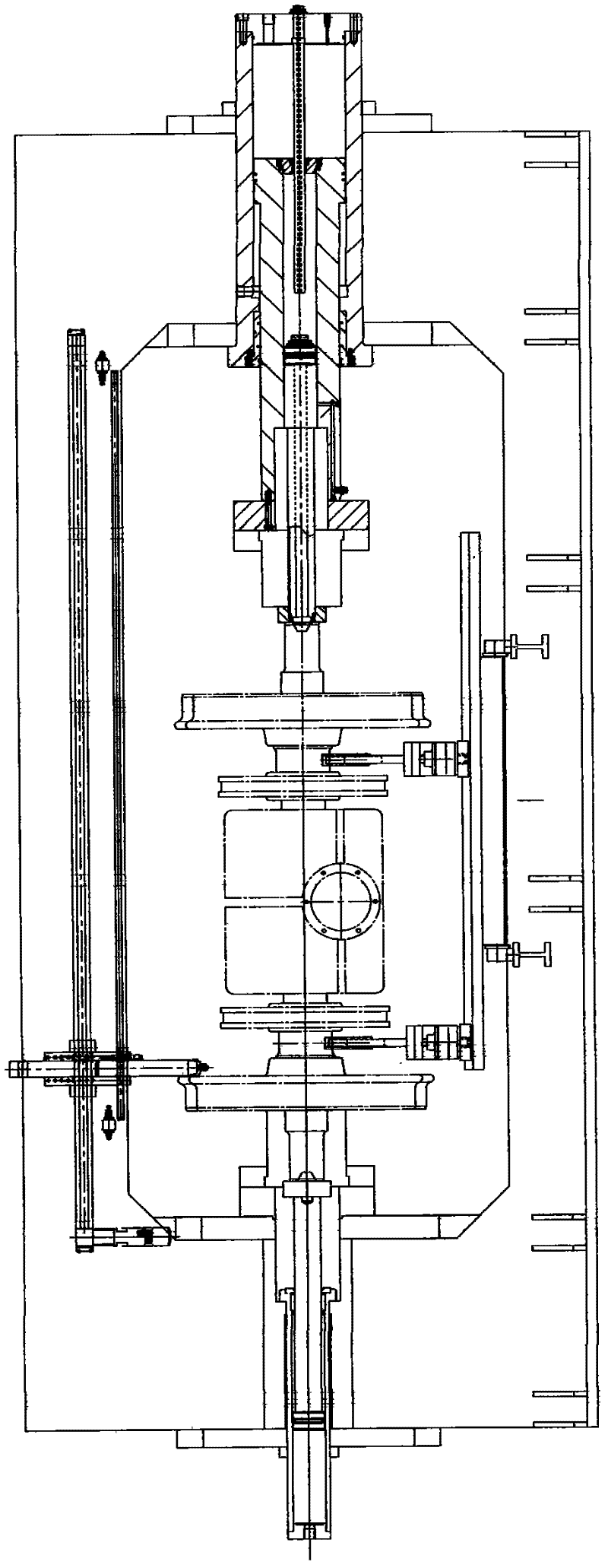
[0015] The present invention will be further described below in conjunction with the accompanying drawings. Such as Figure 1 to Figure 7 As shown, the present invention discloses a center hole positioning wheel set press-fitting machine, which includes a frame 1 and an oil cylinder device arranged axially symmetrically inside it, a thimble device 2, a trolley 3, a detection device 4, a hydraulic system, and an electric control system. It is characterized in that: one end of the oil cylinder device is the main pressure oil cylinder 5, and the other end is the auxiliary oil cylinder 6, a large piston rod 51 is arranged in the main pressure oil cylinder, a small piston rod 52 is arranged in the large piston rod, and the end of the large piston rod is The right indenter seat 7 is installed at the top, the thimble device 2 is installed at the end of the small piston rod, and the thimble device 2 is installed at the end of the piston rod of the auxiliary oil cylinder, and the left ...


PUM


Abstract

The invention discloses a central hole positioning wheel pair press mounting machine, which comprises a machine frame, an oil tank device, thimble devices, a trolley, a detection device, a hydraulic system and an electronic control system, wherein the oil tank device, the thimble device, the trolley, the detection device, the hydraulic system and the electronic control system are axially and symmetrically arranged in the machine frame; one end of the oil tank device is provided with a main pressure oil tank; the other end of the oil tank device is provided with an auxiliary oil tank; a big piston rod is arranged in the main pressure oil tank; a small piston rod is arranged in the big piston rod; a right pressure head base is arranged on the end part of the big piston rod; a thimble deviceis arranged on the end part of the small piston rod; a thimble device is arranged on the end part of a piston rod of the auxiliary oil tank; and a left pressure head base is sleeved outside the auxiliary oil tank and is fixed on the inner side at the left of the machine frame. When the central hole positioning wheel pair press mounting machine is compared with a dual-head oil tank press mounting machine, a movable beam and an inserting plate as well as a positioning groove (hole) and a locking mechanism are eliminated, so the structure and a control part are simplified; and the auxiliary oil tank at the other end is very small, so the cost is reduced. When the central hole positioning wheel pair press mounting machine is compared with a lengthened rod and pendulum press mounting machine, press mounting is finished through central hole positioning, so a shaft and a shaft end are not damaged, and the press mounting quality and the train safety are improved.

Description

technical field [0001] The invention relates to equipment machinery for railway locomotives, suitable for wheels of locomotives with different gauges such as meter gauge, quasi-gauge, wide gauge, urban rail transit (subway, light rail), passenger cars with 2 to 3 brake discs, ordinary freight cars, etc. , axles, brake discs, reduction boxes or similar parts assembly, pressure inspection or extrusion test and back pressure test. It is especially suitable for fully automatic press-fitting of high-speed train wheel sets. Background technique [0002] Due to the rapid development and widespread use of high-speed trains, the design of wheel sets has been continuously updated, and higher requirements have been placed on their assembly and disassembly, which in turn has led to continuous follow-up and innovation of corresponding equipment machinery. At present, there are two basic types of corresponding press-fitting and unloading machines: one of them is a single-head oil cylinde...

Claims


Application Information

Patent Timeline
Patent Type & Authority Applications(China)
IPC IPC(8): B23P19/027
Inventor 喻国锋范鸿童俊军张霄童光董婷婷
Owner HUBEI HEQIANG MACHINERY DEV LIMITED BY SHARE
Learn More