A clamping mechanism of a plastic injection molding machine
An injection molding machine and mold locking technology, which is applied in the field of plastic injection molding machines, can solve the problems of large overall volume of the mold locking mechanism, long length of the mold locking mechanism, and large floor space, so as to achieve concentrated force on the mold and improve the pass rate , Improve the effect of the stress condition
- Summary
- Abstract
- Description
- Claims
- Application Information
AI Technical Summary
Problems solved by technology
Method used
Image
Examples
Embodiment 1
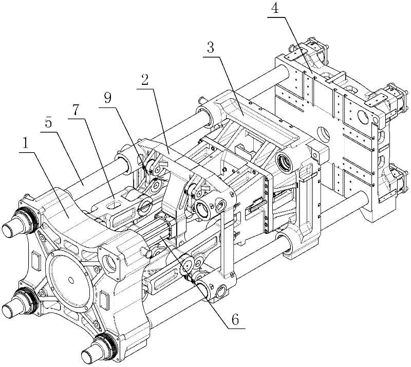
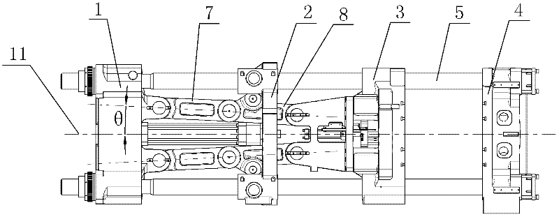
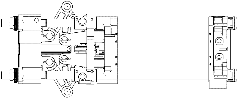
[0018] Embodiment 1: As shown in the figure, a mold clamping mechanism of a plastic injection molding machine includes a base 1, a thrust seat 2, a movable template 3 and a fixed template 4, which are arranged in sequence and whose centers are located on the same central axis 11, and the base 1 A guide rod 5 is fixedly arranged on the top, the thrust seat 2 and the movable formwork 3 are sleeved on the guide rod 5, the fixed formwork 4 is fixedly connected to the end of the guide rod 5, and the thrust seat 2 includes a frame formed by four connecting ribs 21. The outer frame, the corner of the outer frame is integrally provided with a guide seat 22, the guide seat 22 is sleeved on the guide rod 5, and a connecting rod 23 is integrally connected between a group of connecting ribs 21 arranged oppositely among the four connecting ribs 21. The rod 23 passes through the center of the thrust seat 2, and an oil cylinder 6 is fixedly installed on the connecting rod 23 at the center of ...
Embodiment 2
[0019] Embodiment 2: As shown in the figure, other mechanisms are the same as Embodiment 1. The difference is that among the four connecting ribs 21 of the thrust seat 2, two sets of connecting ribs 21 that are oppositely arranged are uniformly connected with connecting rods 23, two The intersecting portion of the connecting rods 23 is located at the center of the thrust seat 2 , and the oil cylinder 6 is fixedly installed at the intersecting portion of the two connecting rods 23 .
[0020] In the above-mentioned embodiment, the included angle θ can be selected according to actual design needs in the range of greater than 0° and less than or equal to 10°; When the connecting rod 23 is connected, two oil cylinders 6 that are symmetrical along the central axis 11 can be fixedly installed on the connecting rod 23, or three oil cylinders 6 can be fixedly installed on the connecting rod 23, and one of the oil cylinders 6 is located on the connecting rod 23. At the center of the thr...
PUM
 Abstract
Description
Claims
Application Information
 - R&D
- Intellectual Property
- Life Sciences
- Materials
- Tech Scout
- Unparalleled Data Quality
- Higher Quality Content
- 60% Fewer Hallucinations
Browse by: Latest US Patents, China's latest patents, Technical Efficacy Thesaurus, Application Domain, Technology Topic, Popular Technical Reports.
© 2025 PatSnap. All rights reserved.Legal|Privacy policy|Modern Slavery Act Transparency Statement|Sitemap|About US| Contact US: help@patsnap.com


